LIBRARY
A WBG-Based Three Phase 12.5 kW 500 kHz CLLC Resonant Converter with Integrated PCB Winding Transformer

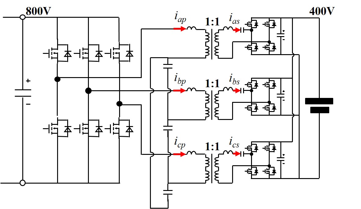
By redistributing the primary and secondary windings on the outer posts and adding a center post, the leakage inductance of the transformer can be increased, and serves as the primary and secondary side resonant inductors. Compared to other integration methods, the interleaved winding structure is maintained, and thus a smaller ac winding loss is achieved. Also, with the additional center post serving as the leakage flux path, the leakage inductance (resonant inductors) can be controlled by adjusting the center post air gap length. In addition, all the leakage flux is confined in the center post, having no impact on the surrounding components. If we investigate the flux in the core, due to the 120° phase shift between each phase, the flux in the three center posts also have 120° phase shift. As a result, the total flux in the center posts is cancelled out. This can be verified through 3D finite element analysis simulation. We can see that the flux in the three center posts is almost zero. Therefore, we can simplify the transformer structure by removing the three center posts.
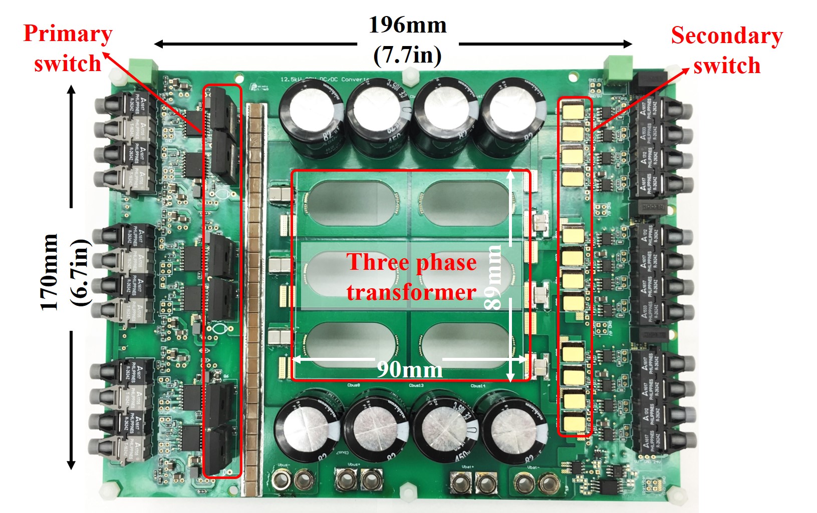
Using the designed three-phase integrated transformer, a 12.5 kW hardware prototype with 500 kHz switching frequency is developed, as shown in Fig. 2. The resulting power density, including the heatsink, is 155 W/in3. This power density is much higher than the single phase version, due to the three-phase transformer integration. The efficiency of the three phase CLLC resonant converter is also tested, and we can see that the peak efficiency of 97.3 percent is achieved.


