LIBRARY
A Series-Series-CL Resonant Converter for Wireless Power Transfer in Auxiliary Power Network

As shown in Fig. 1, an S/S-CL topology is proposed to meet all the requirements for the WPT as the auxiliary power supply. Capacitor C1 is in resonance with the self-inductance of the primary side coil L1 working as a constant current source. The capacitor C2 is used to adjust the load impedance of the full-bridge inverter to reduce reactive power and achieve ZVS for primary-side MOSFETs. The CrLr pair will change the constant current (CC) source to a constant voltage (CV) source, forming a load-indepen- dant voltage source. This topology can thereby achieve coupling- independent resonant frequecy and load independent output volt- age, and the output voltage can be adjusted by changing a pair of LC parameters.
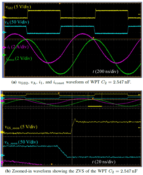
Fig. 2 shows the gate signal, jumping node voltage, and current of both the primary and secondary side. From the zoomed-in wave- form, ZVS is achieved for soft switching, and I1 is almost in-phase with VA, which means the system reactive power is minimized.


