LIBRARY
High-Frequency PCB Winding Transformer With Integrated Inductors for a Bi-Directional Resonant Converter

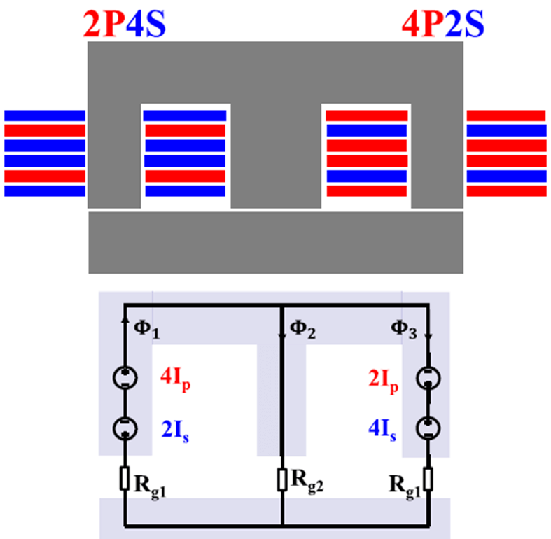
Fig. 1 shows the winding structure of a proposed integrated transformer. In the paper, the reluctance model shown in Fig. 1 is clearly explained. The benefits of the proposed EI core transformer structure are obvious. The leakage flux is controlled by the reluctance of the center leg air gap. If the center leg air-gap reluctance is large, less leakage flux will flow through it, resulting in smaller leakage inductance. If the center leg air-gap reluctance is small, more leakage flux will flow through it, resulting in larger leakage inductance. In addition, compared with a conventional transformer, the leakage flux in the proposed magnetic structure is confined within the core instead of in the air. The confined flux can help with radiated EMI and reduce eddy current loss in the surrounding metals.
A transformer winding loss model based on two-dimensional finite element analysis (FEA) simulation is built to quantify the impact of magnetizing current and fringing. Transformer core loss can be calculated by the Steinmetz Equation, which is not only related to the transformer dimensions, but also related to the leakage and magnetizing inductances. With both winding loss and core loss, the total transformer loss can be calculated.
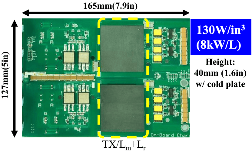
A 6.6 kW, 500 kHz on-board battery charger dc/dc stage prototype is built to verify the proposed PCB transformer structure and optimization procedure, as shown in Fig. 2. A 1.2 kV SiC device from GE is used as the primary-side switch, and GS66516T from GaN systems is used as a secondary-side switch. The prototype has 130-W/in3 power density, including the heatsink with 97.8 % peak efficiency. The experimental results verify the proposed concept.


