


LIBRARY
Phase Shedding Control and Circulating Current Analysis of Two-Channel Paralleled Soft-Switching Three-Phase Inverter
Year: 2021 | Author: Gibong Son | Paper: S9.4
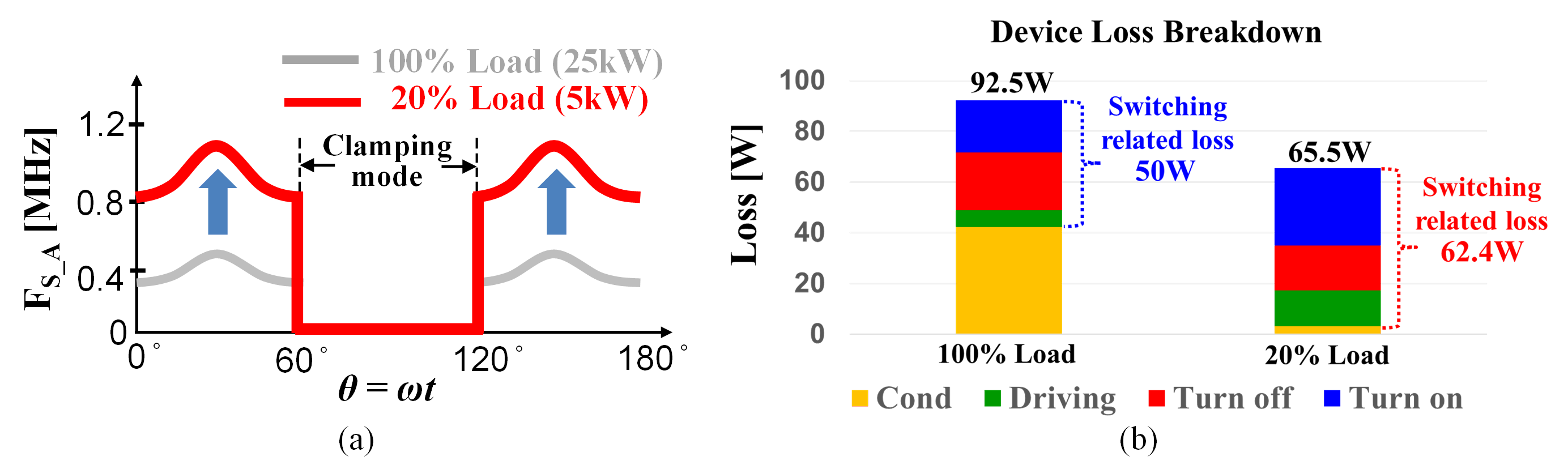
Fig. 1. (a) Phase A switching frequency (b) Device loss breakdown under full and 20% load conditions.
The current handled by each channel becomes smaller at light load and the switching frequency of the inverter increases dramatically due to its CRM-based operation as shown in Fig. 1(a). This brings about high switching-related loss. As shown in Fig. 1(b), at 20% load, theswitching-related loss is not only high, but also dominant. Minimization of the switching-related loss is the key to improve the light load efficiency.
%nbsp;The main concept of the proposed control for light load efficiency improvement is to lower the switching frequency by increasing the current that is handled in the first channel (CH1). No gate signals are given for the entire switchesin channel 2(CH2), so-called phase shedding. With the phase shedding, the switching frequency drops significantly because of the increased current in CH1. Another benefit is the number of switches running at high frequency halves due to the no switching action in CH2. This also greatly reduces the switching-related loss.
%nbsp;By the way, despite no gate signals given in CH2, some current flows through CH2 during the clamping mode. The current does not deliver any energy to the output. It only circulates between CH1 and CH2 rendering the rms value of the inductor current in CH1 larger. When one phase is clamped, the corresponding switchs body diode in CH2 is forward-biased. Switching status in CH1 affects inverter output voltage in CH2 because two channels share the zero- sequence voltage.
%nbsp;The solution for the issue is to enable the clamping mode phase in CH2. In Fig. 2(a), the gate signal is given in phase A in CH2 the same as CH1 and only the gate signals in CRM and DCM phases (phase B and C) in CH2 are not given. In this way, the currents in CH1 and CH2 converge to each other after entering clamping mode as shown in Fig. 2(b). Eventually, the circulating current is removed and currents in both channels deliver power to the output. This control method improves light load efficiency by 0.8%- 2.4%.
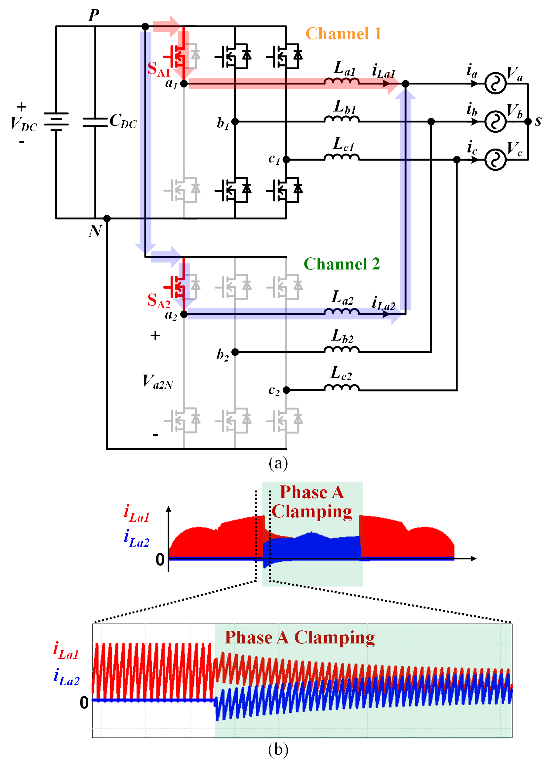
Fig. 2. (a)New phase shedding method (b) Removal of the circulating current.
