


LIBRARY
11 kW Bidirectional On-board Battery Charger
Year: 2021 | Author: Hieu Pham | Paper: S7.3
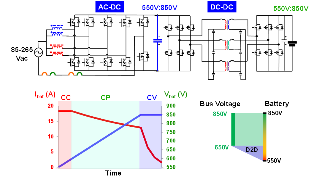
Fig. 1. The system structure of 11kW on-board charger (a) and battery charging profile (b).
Fig. 1. In this paper, the design considerations of the two-stage on-board charger are introduced, including the optimization of PCB-based magnetic design and the control strategy between stages.
A 11 kW on-board charger prototype with 57W/in3 power density is demonstrated and the efficiency of the system is above 96% over the whole battery voltage range, as shown in Fig. 2.
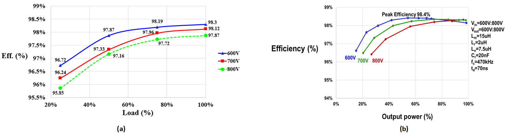
Fig. 2. The overall efficiency of the system: (a) ac/dc stage and (b) dc/dc stage.
