


LIBRARY
Modeling and Control of Modular Multilevel Converter
Year: 2021 | Author: Yugal Gupta | Paper: S12.5
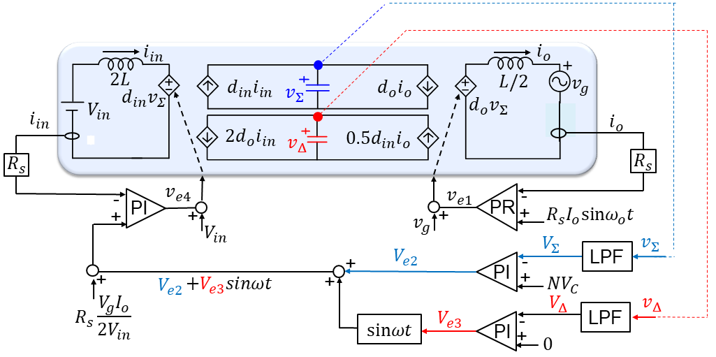
Fig.1. Interpretation of Control Implementation Proposed by Akagi et al. using Decoupled Equivalent Circuit Model
Moreover, from the equivalent circuit, two kind of circulating energies, related to 𝒱 ∑ and 𝒱 Δ are identified. The circulating energy related to 𝒱 ∑ exchanges between input and output while the circulating energy related to 𝒱 Δ merely swaps between the upper and lower arms in MMC. Further, two "ideal" control laws, diniin=doio and 2diniin=0.5doio are established to make the circulating energies related to 𝒱 ∑ and 𝒱 Δ zero, respectively. Using these control laws, the control strategies, so far existing in the literature to reduce the circulating energies, are easily interpreted.
Furthermore, to quantitively visualize the existing circulating energies in each control strategy, the state plane between arm current and arm capacitor voltage (i&u-N𝒱 cu) is drawn where the area enclosed by the state trajectory is related to the circulating energy. Furthermore, the state plane between upper and lower arm capacitor voltages is drawn to quantify the circulating energy related to 𝒱 ∑ and 𝒱 Δ separately. Fig. 2 shows the state planes for (a) Akagi's control (b) improvement based on 2nd harmonic current injection (c) Voltage gain control, and (d) 2nd harmonic current injection together with voltage gain control. From the state planes, the improvement in terms of the circulating energies can be easily observed.
Therefore, with the help of proposed circuit and state planes, the generally accepted control framework as well as various control strategies to reduce the circulating energies are easily interpreted.
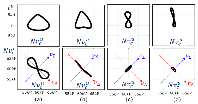
Fig.2. State planes in various control strategies
