LIBRARY
Modeling and Impedance Analysis of a Turbine-Generator-Rectifier System with Electromechanical Dynamic Interactions in More Electric Aircraft

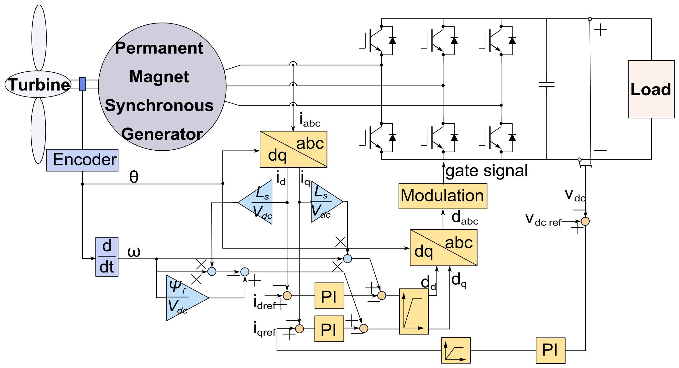
In this paper, an onboard HVDC system is studied, as shown in Fig. 1. The permanent magnet synchronous generator is rated at 1 MW, the dc bus voltage is rated at 1 kV. A dual-loop control strategy is applied to the generator, where the outer loop regulates dc bus voltage with a PI controller and provides the reference for iq, and the reference of id is set as 0 to achieve unity power factor control. The turbofan shaft is emulated using the open- source AGTF30 advanced geared turbofan engine system model. Multiple loads are connected to the dc bus through power electronics interface, which can be modeled as constant power loads.
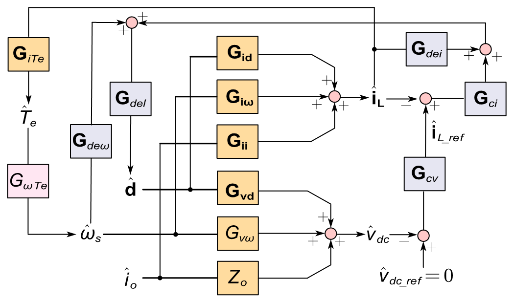
Here the impedance-based stability criterion is used to access the stability condition of the dc distribution system. Therefore, to access the turbofan shaft dynamics' impact on system stability, it is necessary to derive the small- signal impedance of the source subsystem. The small signal model is shown in Fig. 2. It is found that the difference of the closed-loop output impedance in the case where shaft dynamics is considered and ignored lie in the three terms,Gde?GTe, Gv?GTe, and Gi?GTe, which are found to be so small that the difference is negligible. It is also found that when the generator power ratio to the total turbofan power increases, the turbofan shaft dynamics have more impact, though still small, on the output impedance below 10 Hz, at which the source subsystem seldom has dynamic interactions with the load subsystem.
This paper provides a detailed analysis of the shaft dynamics of the turbofan's impact on the small-signal stability of the aircraft dc distribution system and reveals the masking effect of the rectifier for the following reasons: the speed perturbation has small impact on the dc bus voltage and stator current; the turbine dynamics is small with the current speed controller; the decoupling terms in the current controller attenuates the speed perturbation impact; and the dc voltage control reduces the impedance gain at low frequency, which further reduces the potential stability impact from mechanical dynamics.


