LIBRARY
High power transformer with controllable leakage inductance

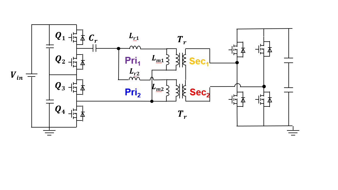
This paper focuses on the transformer design for the dc-dc stage. The transformer turns ratio is selected to be 0.563 based on the input and output voltage range. UI Core is selected based on needed leakage inductance. Different winding structures' impact on leakage inductance is analyzed and finally leakage inductance is achieved by properly breaking the interleaved winding structure without sacrificing too much winding loss.
The transformer turns number is determined based on the transformer loss volume trade-off and core loss winding loss trade-off. Different core loss density's impact on transformer design is also analyzed based on a similar method.


