


LIBRARY
Design Optimization of PCB winding Matrix Transformer for LLC Converter
Year: 2021 | Author: Pranav Raj Prakash | Paper: S2.3
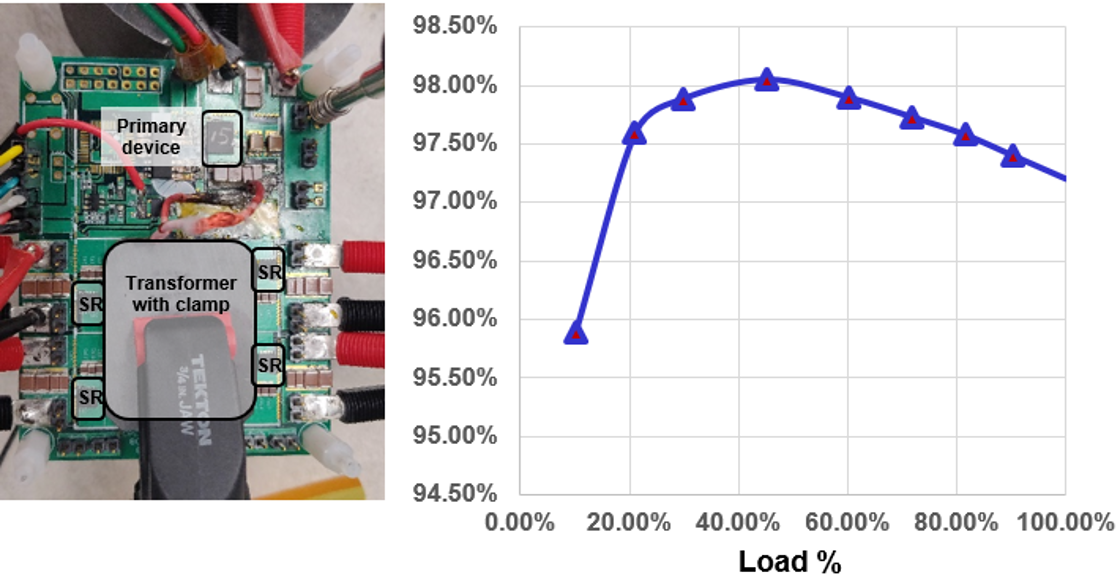
Fig. 1. Test Hardware and converter efficiency.
CPES designed a 400V/12V half-bridge LLC dc-dc converter with a planar matrix transformer and center-tap secondary rectifiers running at 1 MHz with a peak efficiency of 97.6% and a full load efficiency of 97.2%. To further improve the efficiency while maintaining the same power density, the switching frequency of the converter was swept from 200 kHz to 1.6 MHz and the transformer loss was evaluated versus magnetic footprint. It was found that the transformer loss is similar from 600 kHz to 1 MHz, but since the device switching losses increase with switching frequency, the lower frequency of 600 kHz has better overall converter efficiency. Subsequently, the 400V/12V LLC converter was redesigned for switching frequency of 600 kHz and a peak efficiency of 98.05% and a full-load efficiency of 97.2% was obtained, as shown in Fig. 1.
Upon closely examining the thermal performance of the converter it was observed that the temperatures of the secondary devices were not uniform, as shown in Fig. 2. This indicated that there are current-sharing issues between the four parallel secondary windings that conduct together in one switching cycle. This was reiterated by comparing the drain-source voltages of the parallel SRs, where it could be seen that the body diodes of the SRs stop conducting at different times, indicating different currents flowing through each device. A few factors causing this issue have been discussed in detail in this paper, such as proximity of the winding to the air gap of the transformer and the proximity of the conducting secondary layer to the conducting shield layer. A possible solution will also be presented.
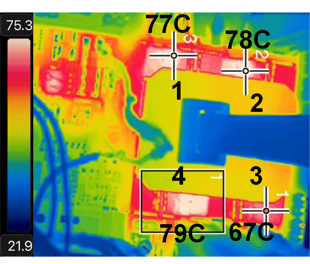
Fig. 2. Temperatures of SRs when converter running at full load.
