LIBRARY
Three-phase Multi-level Inverter Topology Evaluation

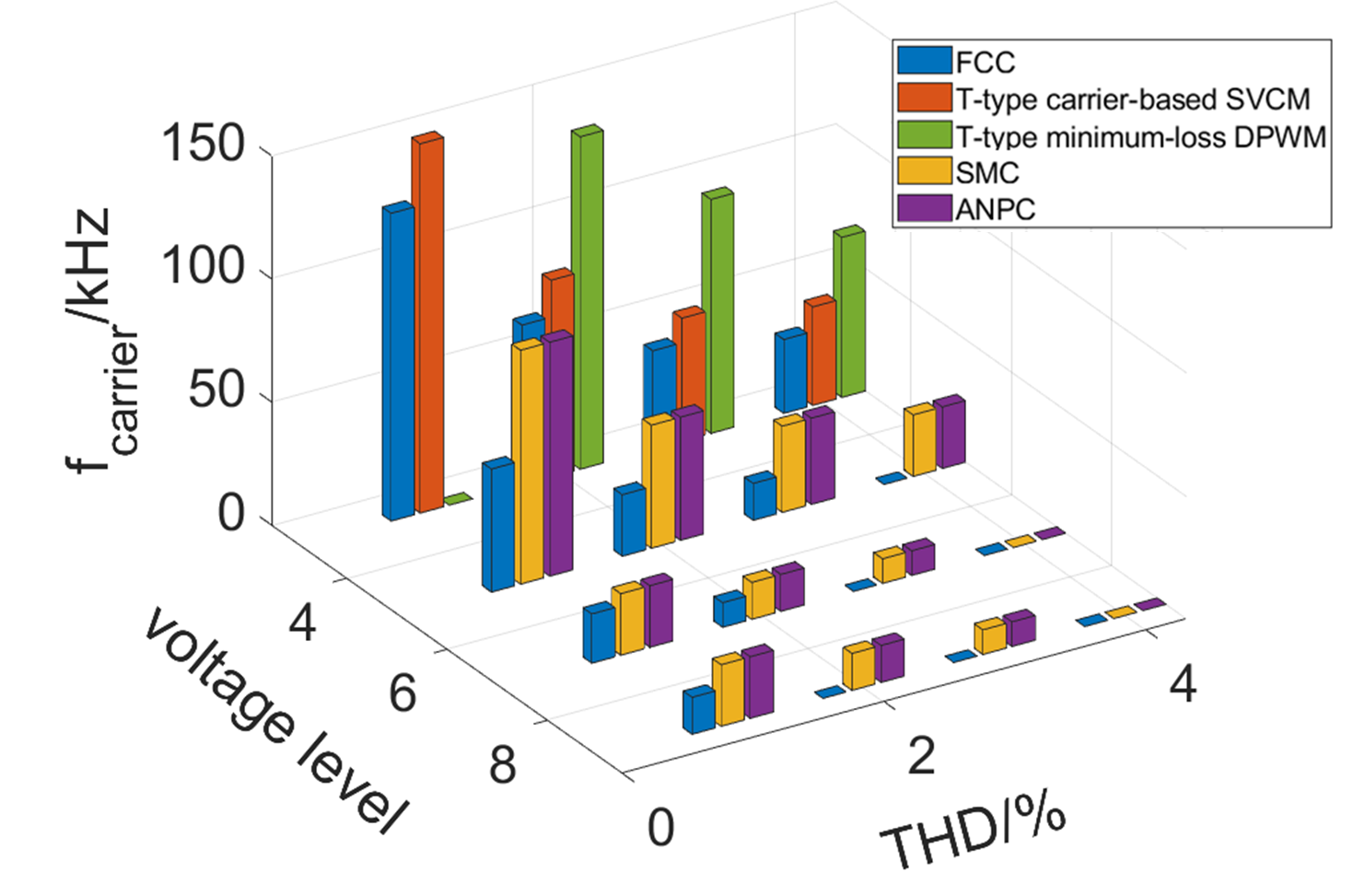
Three topologies shown in Fig. 1 are selected. Flying capacitors (FC) are widely adopted in high voltage and medium voltage applications. Recently it is also proposed in lower PV applications and can achieve high efficiency due to the adoption of low voltage GaN devices. However, the power density is sacrificed with the increasing number of floating capacitors. Therefore, some hybrid topologies seven-level stacked multi-cell (SMC) and active neutral-point converters (ANPC) are also be compared. Evaluation starts from three-level to nine-level. Loss evaluation includes the semiconductor and floating capacitors. Both GaN devices and SiC devices are con-sidered to achieve the best performance. Volume evaluation includes the cooling system and floating capacitors. For the EMC filters, an initial comparison of noise spectrums of common-mode voltage and differential-mode current is simulated of each topology to avoid numerous filter designs and comparisons. All these compared parameters are related to the carrier fre-quency and modulation method of each topology. For a fair comparison, carrier frequencies un-der the same THD values are extracted as shown in Fig. 2. It can be observed that for FC, from three-level to five-level, the frequency decreases most. While for the other two hybrid topologies, the frequency decreases most from five-level to seven-level.


