


LIBRARY
Design of a High-Frequency Transformer and 1.7 kV Switching-Cells for an Integrated Power Electronics Building Block (iPEBB)
Year: 2022 | Author: Narayan Rajagopal | Paper: T-S1.5
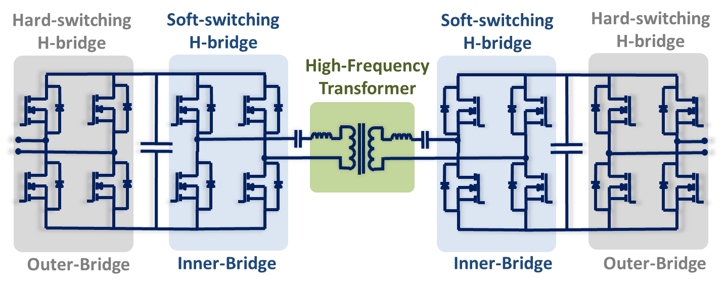
Fig 1. iPEBB di-directional topology with the transformer highlighted in green.
In conventional medium-voltage transformers, the insulation can become a sizeable fraction of the transformer weight and present a thermal barrier preventing effective cooling. To address this, the proposed transformer design uses an insulating sheet to separate the primary- and secondary-sides (Fig 2 (a)). The sheet is coated with conductive and semiconductive layers to reduce the electric field strength. Mica is used as the insulating sheet and has dimensions to meet the primary-to-secondary voltage insulation and creepage requirements. The insulating sheet is covered with a layer of conductive paint on the two surfaces where the primary and secondary coils and core sections are located. The conductive layers are referenced to the potentials of the two respective sides, thereby eliminating electric field stress in the air gaps around the windings (Fig 2 (b)). N49 ferrite was used for the core, and 6600/46 AWG litz wire was used for the windings. Based on initial test results, the transformer is expected to have core losses of 300 W and winding losses of 850 W at 250 kW, resulting in an efficiency of 99.5%. Future work will involve testing the transformer with the rest of the iPEBB converter.
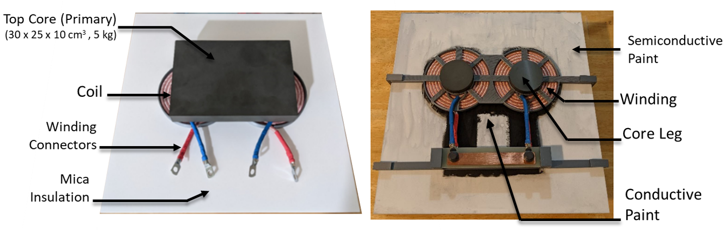
Fig 2. Top view of the transformer prototype (a) before the conductive and semiconductive paints is applied, (b) with the top core block removed to show the Litz wire coils and conductive (black) and semiconductive paint (white) paints.
