LIBRARY
Investigation and Solutions for High Termination Losses in Planar Matrix Transformers with Full-Bridge Rectifiers

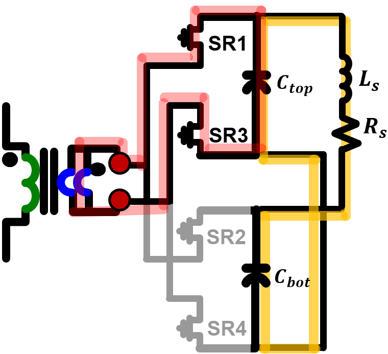
However, in this termination, the output filter capacitors must be split between the two secondary layers as Ctop and Cbot respectively, and must be paralleled using vias before connecting to the load. This results in a long paralleling path, which has its own parasitic leakage inductance Ls and resistance Rs, as shown in Fig. 1. Due to parallel resonance between the two parallel capacitor paths, there is high circulating currents at the resonant frequency, which depends on Ls and Ctop. This results in high current through Rs, resulting in high termination ac resistance at the parallel resonant frequency. Hence, it must be moved to a higher frequency away from the converter switching frequency to minimize its impact on the converter performance.
To achieve this, additional interleaving vias can be added directly under the capacitors to provide a much shorter path with lower Ls, and hence, higher parallel resonant frequency. This concept was experimentally verified by comprehensively modeling and measuring the transformer impedances with the different capacitor-paralleling via placements. Moreover, to verify its impact on the converter efficiency, a 2 kW 500 kHz unregulated 112 V/14 V LLC converter was developed, and full-load efficiency improvement of 0.56% was obtained, as shown in Fig. 2.
In conclusion, this paper proposes a guideline to design the termination for PCB-winding based planar matrix transformers with full-bridge rectifiers. The paralleling of the split output-filter capacitors in the SR on-winding termination results in parallel resonance, which could impact the transformer resistance, and hence, converter efficiency if not designed properly. The improvement in transformer ac resistance, and hence LLC converter efficiency are demonstrated with the improved termination design.


