Fig. 1. Comparison of the output voltage of three voltage source inverters
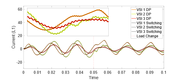
With increase in the deployment of distributed and renewable energy resources, application of power electronics as power processing units between sources, loads and energy storage systems has also increased. To ensure better design, stability, and sustainability of power grid in the future, simulations of large-scale interconnected power electronics units are essential. In this work a time-frequency domain approach known as dynamic phasor method is represented and an application of this method in parallel combination of single-phase voltage source inverters is expanded to a general form with any number of interconnected converters. For modeling this system, time-varying Fourier representation of the differential equations that represent all the state variables of individual VSIs in different load conditions are formed, then using the DP representation of components at point of common coupling, all the equations that describe any number of VSIs are coupled to represent the completed model for any number of parallel connected converters. This methodology is then numerically validated with comparing to the detailed switching modeling method and is used to model up to 100 parallel connected converters. An approach for comparing the accuracy and computational efficiency of this method with detailed switching model is presented and computational efficiency of this modeling method is compared with the detailed switching model in terms of time step comparison that showed in the experiment case, DP modeling method can have 16.6 times larger time-step in comparison to the switching model with similar value of RMS error rate. Accuracy of this method is compared with the detailed switching model that in time and frequency domain and also a test case is designed to model between 5 to 100 parallel connected voltage source inverters to compare the computational efficiency of the model with the detailed switching model Multiple time domain and frequency domain representation of modulator including multi frequency modulation signal modulators is also used in this modelling method to expand the capability of conventional DP method in observing the instability cases that are invisible to average models but visible to switching and dynamic phasor-based models that opens the space for applying this modeling method to large-scale converter networks while providing better understanding of harmonic content and more reliable simulation results.
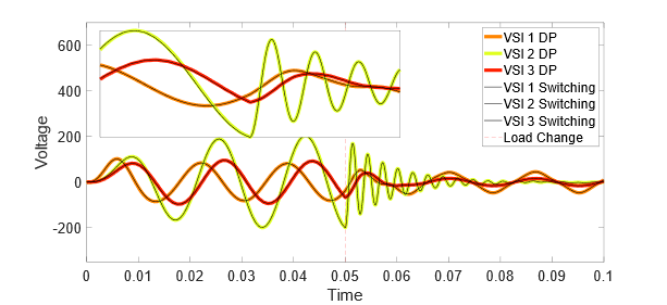
Fig. 2. Measurement of accuracy of detailed switching model


