


LIBRARY
Transient Voltage Suppression (TVS) Diode-based Protection for 10 kV SiC MOSFET in 3 Phase 7-level 1.1 MVA, 13.8 kVac, 22 kVdc Multicell Power Converter
Year: 2023 | Author: Arthur Mendes | Paper: H4.4

Fig.1. Multicell converter (a) Cell types (b) Cell Short-Circuit Fault Model and test circuit.
Fig.1 (b) presents the model for the CSCF occurring at the end cell, nearest the AC terminals. The dynamic of the short-circuit is defined by the R-L-C network in which the L is the stray inductance of the converter bus, C is capacitance is from the flying capacitor itself and R is the residual resistance of the defective switches. To limit overvoltage stress and cell failure during fault, a clamping circuit based on high energy capability TVS diode is inserted in parallel with the switches. The TVS diode current discharges the capacitor Cf4 and maintains the cell voltage under its rated value. Additionally, an experiment was conducted using the converter bus, an external resistor, and a high voltage relay to emulate the short-circuit. The results are shown in Fig. 2 where the Cf5 voltage (blue) decreases and the adjoining cell voltage increases proportionally during fault. When the cell voltage reaches the TVS-diode breakdown threshold, a fast current spike discharges capacitor Cf4 maintaining the voltage at the switch lower than 5 kV.
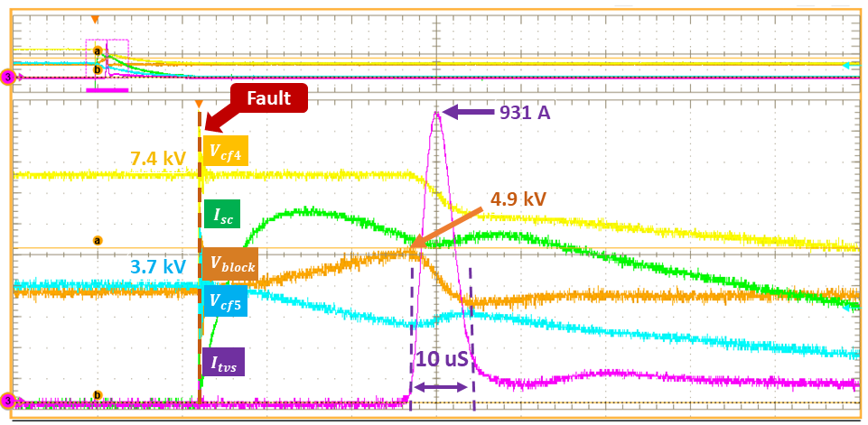
Fig.2. Test waveform at rated cell voltage 3.7 kV, showing V_cf4 (yellow), V_cf5 (blue), I_tvs (purple), I_sc (green).
