LIBRARY
Utilization of EMI Shielding in PCB Matrix Transformer for Inductor Integration for High Power Density Resonant Converter

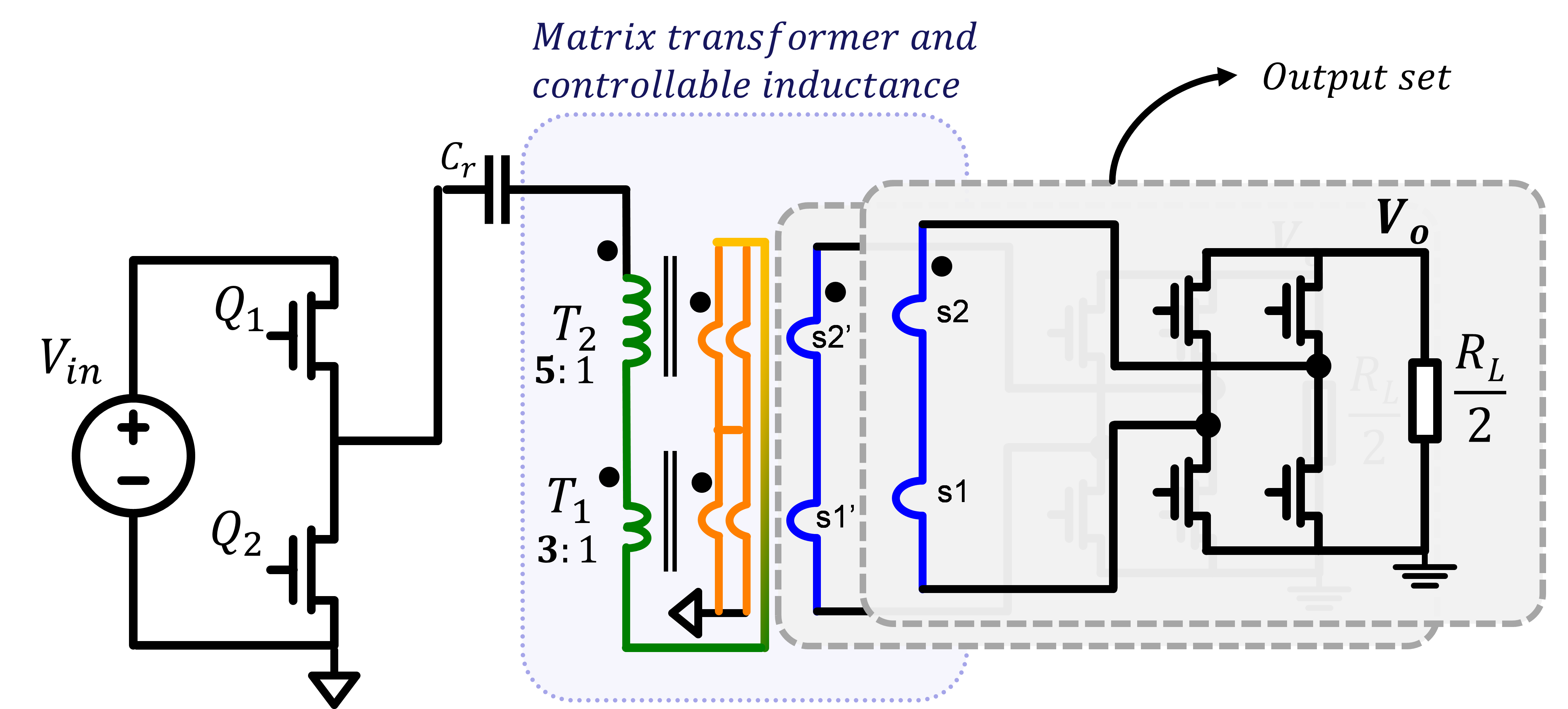
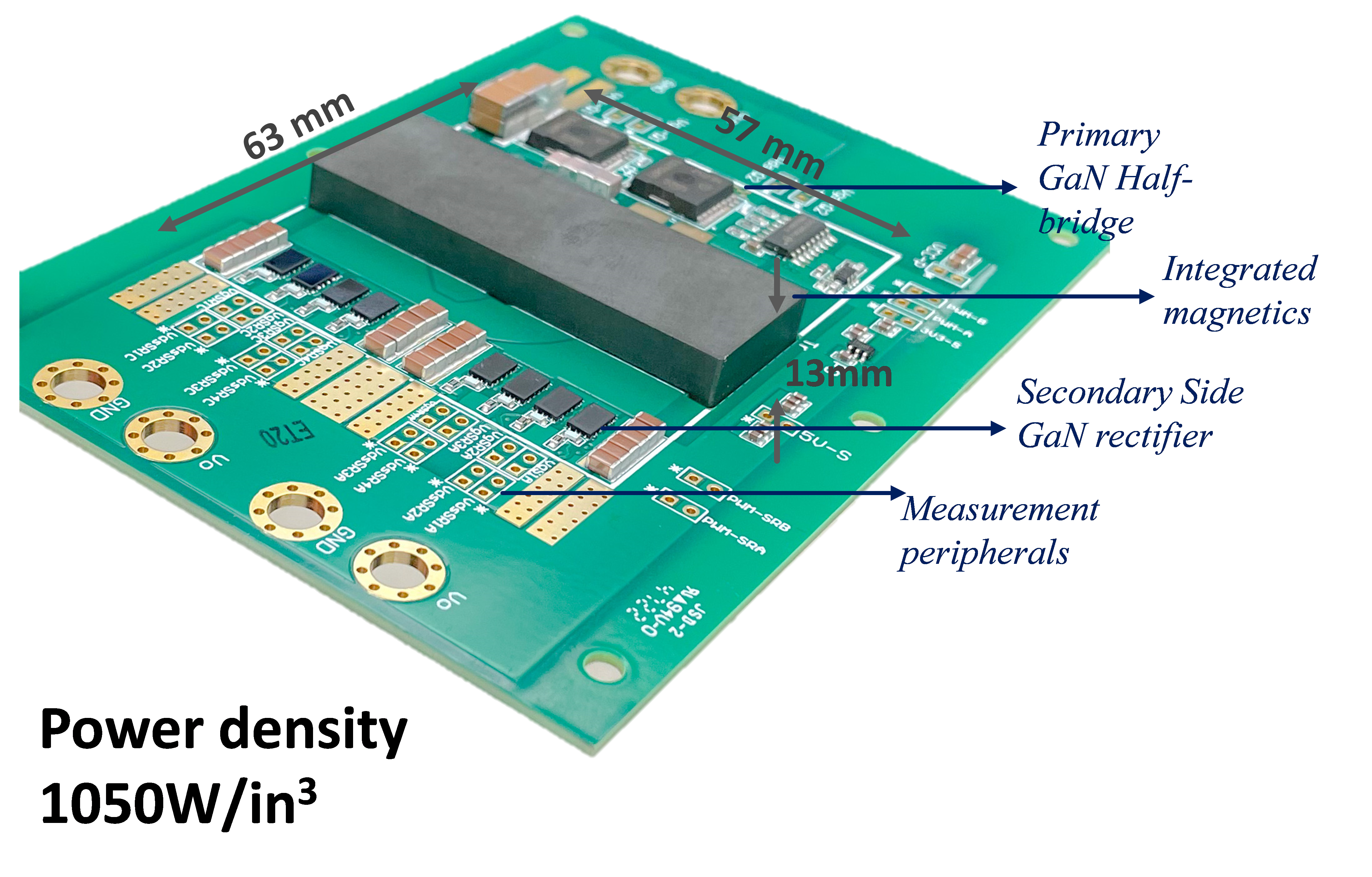
Magnetic integration of the printed circuit board (PCB) transformer is imperative for achieving a high-efficiency dc-dc converter for the off-line power supply. This paper proposes a method of integrating controllable leakage inductance within a PCB-based matrix transformer. The inductor is created by unbalancing the turns ratio between the two elemental transformers. A new method is proposed for the PCB winding implementation by utilizing the electromagnetic interference (EMI) shielding layers to create resonant inductance. The proposed method increases the utilization of the PCB winding from 66% to 100%, which increases the throughput of the PCB transformer, where all layers, including shielding layers, are utilized as windings. Furthermore, the DC resistance and the winding loss are reduced compared to the state-of-the-art implementation, and higher power density is obtained. The created leakage inductance is controlled and utilized as a series resonant inductance to form a regulated LLC converter. Here, the case study of a 300 kHz 400 V to 48 V regulated LLC converter is presented. The design is based on PCB magnetics, which are easier to manufacture and lower cost than Litz wire magnetics. A prototype for the 400 V/48 V/ 3 kW/ 300 kHz model is demonstrated to have a power density > 1~kW/in3 and peak efficiency of 98.7%.


