LIBRARY
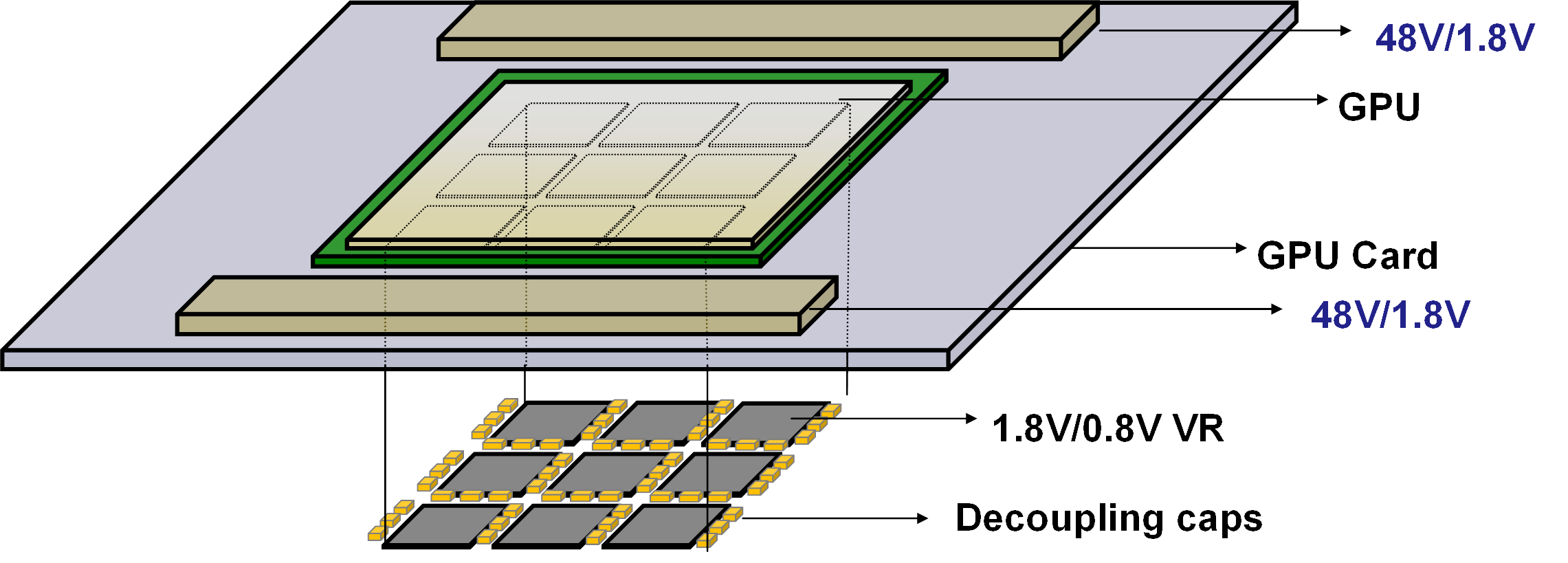
High Current, High Power-Density 1.8V Bus Converter for Vertical Power Delivery to Next-generation SOCs

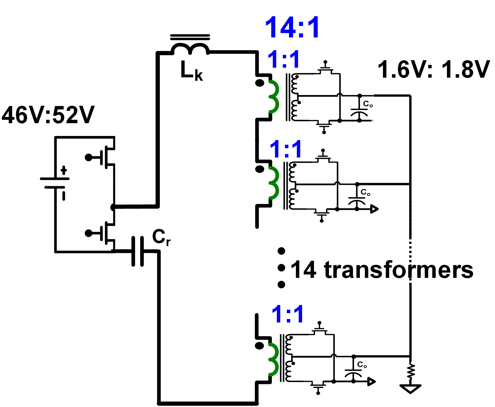
LLC resonant converters are great candidates for such high-efficiency, high-density applications. An 840W LLC converter is built, with the 14:1 transformer being implemented by a matrix of fourteen 1:1 printed circuit board (PCB) -based transformers, the primary windings of which are connected in series, and the secondary windings of which are connected in parallel (Fig. 2). To accommodate the high current, multiple PCB layers must be paralleled for each winding, thereby requiring a 14-layer PCB transformer. The optimal resonant frequency is evaluated to be 600 kHz, at which the converter is switched for maximum efficiency. Since the converter module is installed on the GPU card, only its top side is accessible to cooling. This mandates the placement of all the high-loss-inducing components, including primary and secondary devices, exclusively on the top PCB layer; this results in the need to develop a new termination layout for secondary rectification. Moreover, cooling solutions are developed to effectively manage the temperature of the high-current module.

In conclusion, this paper discusses the design of an 840W 48V/1.8V bus converter module for VPD to GPUs. The LLC converter employs a 14-layer PCB-based matrix transformer for the high turns ratio and high output current. The module is estimated to achieve a peak efficiency of 96.2% and a power density of 2400 W/in3.


