


LIBRARY
Reliable Conductor-Semiconductor Interface for High-Temperature Packaging
Year: 2006
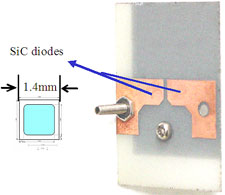
Fig. 1. Temperature embedded chip module.
This barrier has now been broken by CPES research in high temperature integrated power electronics technology. Hard metals, such as molybdenum (Mo) and chromium (Cr), have an almost perfect match to the CTE of SiC, but have very high electrical resistance and are unsuitable as interconnect metal in power electronics. In a new high temperature packaging technology developed, a composite layer of Cu and Cr is electroplated to solve this problem. Cr is used as a buffer layer between SiC and Cu to reduce the high stress due to mismatch in CTE, and Cu to serve as current carrier. The increase in electrical resistance of this composite layer is negligible, while the mechanical stresses are reduced by half an order of magnitude. Furthermore, the metallized interconnects enables constructing a mechanically balanced structure, finally leading to an order of magnitude reduction in thermally induce mechanical stresses.
The technology has been implemented successfully in a two die-module and operated at 250°C.
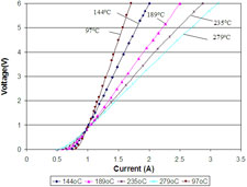
Fig. 2. Forward characteristics.
