LIBRARY
Internal Fault Detection and Isolation for Paralleled Voltage Source Converters

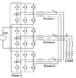
The study on internal fault detection and isolation for paralleled voltage source converters is carried out in CPES in 2008. The example system used for analysis is comprised of three two-level VSCs, a common dc bus, and an R - L load (shown in Fig.1). Two of the converters work together while the third one is a redundant unit, creating a 2 1 system (N 1 redundancy with N=2). Since the possibility of two devices having independent faults at the same time is very low, only single device faults are considered including switch/diode short and open circuits.
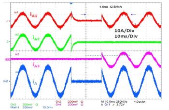
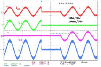
In this study, the potential damages of such faults relating to circulating current were analyzed. Based on the analysis, two kinds of internal faults detection and isolation schemes are proposed, which rely on de-saturation and circulating currents separately. The study confirmed that if the system can be shut down for a short period, SCRs can be used to recovery the system from internal faults with one redundant VSC. Otherwise, the topology with isolated DC buses for each VSC or other fast DC current breakers should be used. Experimental results using a 2 1 VSCs system validated the analysis and protection schemes. The recovery procedure for internal open fault and short are shown in Fig.2 and Fig.3.


