


LIBRARY
Plug-in Hybrid Electric Vehicle Grid Interconnection and Control
Year: 2009
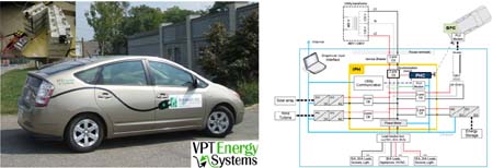
Fig. 1. PHEV with Ni-MH Batteries and System Level, Functional Diagram.
Seen in Fig. 1 is a PHEV conversion, by VPT Energy Systems, and the associated diagram for electrical and control integration into the CPES Sustainable Building Initiative (SBI) that utilizes the PHEV energy storage in conjunction with renewable energy sources connected to the grid to generate a Zero Net Energy Transfer over a yearly average.
The Bi-directional Power Converter (BPC) in the PHEV allows for storage and transfer of the renewable energy to the loads; as seen in Fig. 2, the BPC can seamlessly transfer it's mode of operation from charging to discharging and back. This helps alleviate stress on the grid by providing a subtle transition in power flow and can be used to reduce load peak demand upon the grid. In Fig. 3, the BPC is controlled to adjust its output PF angle to provide VAr compensation to the grid. As such, local VAr generation to compensate the grid to unity PF can be achieved in such a setup.
These features, and others, are implemented in the CPES SBI testbed. Through the system controller, power level and PF requests can be made of the BPC and the converter will respond within nominal limitations.
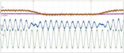
Fig. 2. Unity PF Charging to Discharge back to Charging.
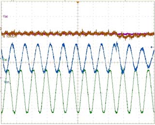
Fig. 3. VAR Compensation from
45° leading PF to Unity PF.
45° leading PF to Unity PF.
