


LIBRARY
Modular Terminal Behavioral EMI Modeling
Year: 2009
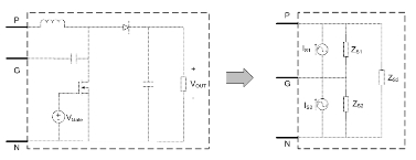
Fig. 1. Example modular terminal behavioral EMI model of a boost converter.
Acquisition of the model is measurement based and manipulated to be used in the frequency domain. The model may be comprised of a complete system or simply a smaller sub-system that can later be pieced together as desired to view the results of an entire system. Typically the detailed model has a component for each part in the system; ETB, however will lump everything together into one Thévenin/Norton equivalent circuit model that forces the terminal characteristics to reproduce the EMI performance of the system. A pre-defined set of measurements are performed: one under nominal operating conditions and another where the low-frequency operation remains constant, but the high (EMI) frequency noise is modified via a different propagation path. With knowledge of how the propagation path changes and the measurement characteristics at the terminals the equivalent circuit parameters are determined.
The terminal EMI characteristics can then be used to predict the EMI in the system which will aid in the selection of system components, design of an optimal filter, and minimizing harmful interactions that may occur between systems.
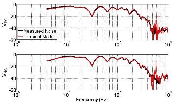
Fig. 2. Experimental vs. terminal modeling results for boost converter.
