


LIBRARY
Common Mode Circulating Current Control of Interleaved Three-Phase Two-Level Voltage-Source Converters with Discontinuous Space-Vector Modulation
Year: 2009
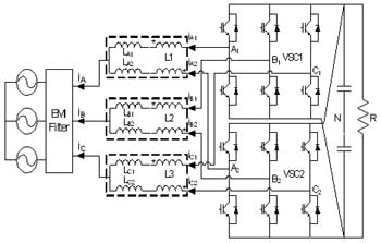
Fig. 1. Paralleled VSCs system with integrated inter-phase inductor.
However, because of the asymmetric of paralleled VSCs in hardware or control, circulating current can be generated, which may increase the power loss, saturate the passive components and even damage healthy devices. The problem is even worse if interleaving and DPWM are used together, because of additional common mode (CM) circulating currents are introduced. Such CM circulating current has a frequency close to fundamental component and is the main reason why interleaving and DPWM are usually considered impossible to be used together in paralleled VSCs system.
This paper presents the control method of common mode circulating current of paralleled three-phase two-level VSCs with DPWM and interleaving.(shown in Fig.1) First, different inductor structures are compared and based on the comparison a new inductor structure with integrated inter-phase inductor and boost inductors is proposed. After that, the main reason of CM circulating current jump in the paralleled VSCs system is analyzed first when DPWM and interleaving are used together. The amplitude of such jump caused by the overlap between different zero vectors relates to system modulation index and interleaving angle. After that, the control method to mitigate such jump by avoiding the overlap of different zero vectors is explained. In addition, for the proposed inductor structure, the method to minimize the core flux by controlling the CM circulating current is shown. Both of the control methods will only introduce very limited additional switching actions, not affecting the system thermal design much. Experimental results shown in Fig. 2 and Fig. 3 have verified the analysis and the feasibility of the control methods.

Fig. 2. output and circulating current with circulating current control.
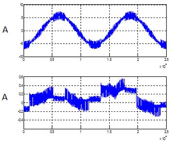
Fig. 3. output and circulating current without circulating current control.
