


LIBRARY
Unified Three-terminal Switch Model for Current Mode Controls
Year: 2010
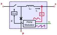
Fig. 1. Common Structure of Current Mode Control Converter.
CPES proposed a unified three-terminal switch model for current mode controls. By identifying the invariant structure in current mode control PWM converter, which consists of active switch, passive switch and closed current loop, the terminal current and voltage relationships are studied and represented by equivalent circuit. Small signal model for current mode control PWM converter, which is good beyond half of switching frequency for forementioned control schemes, can be obtained by simple cyclic permutation and substitution of the PWM switch with its equivalent circuit.
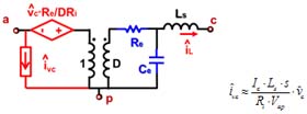
Fig. 2. Three-terminal Switch for Current Mode Control.
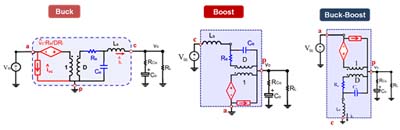
Fig. 3. Applications in familiar converters.
