LIBRARY
Digital Implementation of Driving Scheme for Synchronous Rectification in LLC Resonant Converter

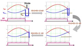
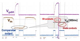
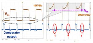
In this digital solution, the drain to source voltage of synchronous rectifier is sensed to determine its paralleled body diode conduction status. Since the forward voltage drop of body diode is much larger than the voltage drop on Rdson of synchronous rectifier, the conduction of paralleled body diode could be easily determined by compared with a threshold voltage Vth. The whole system implementation is shown in Fig.1. The SR tuning process is plotted in Fig.2. When sensing body diode conduction, the comparator output is high, and then FPGA will increase the duty cycle of synchronous rectifier step by step. Finally the body diode will not be conduct. However, there exists potential crisis of over-tuning (cross-conduction), so the duty cycle needs to decrease a bit to let the body diode conducts very small time.


