


LIBRARY
A Simplified Model for Tightly Coupled Transformer with Multiple Windings
Year: 2010
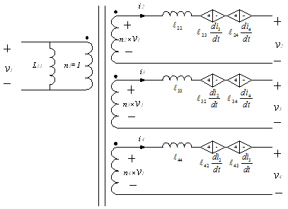
Fig. 1. N-port model for 4-winding transformer.
A schematic diagram for 4-winding transformer in this N-port cross-regulation model is shown in Fig. 1. In this model, the input side has a parallel inductor, which equates to the self-inductance of the primary winding. The secondary side output voltages are the sums of the primary-side voltage times effective turn ratio, the voltage drop on leakage inductance, and all sensed voltages of cross-regulation inductance from other secondary windings. If the winding resistance is not negligible, corresponding winding resistors should be placed in serial with each winding into this model.
