
Fig. 1. Single-phase PWM inverter.
Steady-state error under different load conditions always calls for attention to single-phase PWM inverter (Fig. 1) ac voltage regulation. Different multi-loop linear digital control schemes are comprehensively investigated and compared, both in stationary and synchronous to achieve zero steady-state error under different load conditions, including restive, capacitive, non-linear, or even filter load. PID plus resonant (PID+R) control i and load current feedback (LCF) control improve the steady-state and transient performance respectively, and also leading to the PID+R+LCF control in Fig. 2. Also, the LCF control as well as the capacitor current feedback (CCF) control in Fig. 3 is analyzed further that both of them are subject to control stability issue under resonant loads such as filter loads.
In synchronous frame, imaginary β-axis component generation requires a lot of effort to implement d-q control for single-phase case. A novel d-q frame control strategy in Fig. 4 is proposed eliminating the need for the imaginary component intrinsically, but still attain all benefits of other gneration methods.
The steady-state error presenting in single-phase PLL in Fig. 5 is analyzed and a novel single-phase PLL is proposed in Fig. 6 with internal peak voltage detection to achieve the zero-steady state error.
Experimental results in Fig. 7, 8, 9 are for verification purposes.

Fig. 2. PID+R+LCF control.
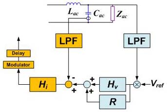
Fig. 3. PID+R+CCF control
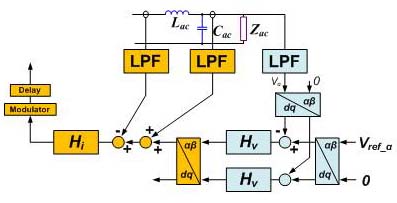
Fig. 4. Unbalanced DQ+LCF control.
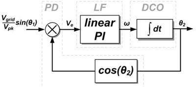
Fig. 5. Conventional single-phase PLL.
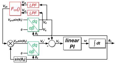
Fig. 6. Proposed single-phase PLL.
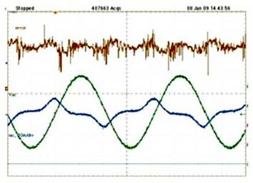
Fig. 7. Unbalanced DQ+LCF control under nonlinear load. AC current (blue), AC voltage (green), voltage error (brown).
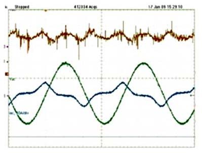
Fig. 8. PID+R+LCF control under nonlinear load. AC current (blue), AC voltage (green), voltage error (brown).


