


LIBRARY
Core Loss Model for Planar Inductor with Non-uniform Flux Pattern
Year: 2011
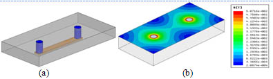
Fig. 1. Lateral flux planner inductor examples (a) 1-turn structure: N=1, (b) 2-turn structure: N=2.
In order to optimize the low profile planar inductor design, inductor core loss need to be studied especially for high frequency applications. From Fig.1 it can be seen that the flux distribution is very non-uniform in this inductor structure. So, the conventional core loss calculation method for discrete inductor, which assumes flux is uniform, cannot be used directly. Furthermore, because some magnetic materials also have very non-linear permeability, such as LTCC ferrite, this problem becomes even more unconventional and complicated.
In order to solve this problem, an analytical core loss model for planar inductor with non-uniform flux and permeability is proposed by CPES. With this method, the planar inductor is divided into many small concentric rings. Fig.2 shows the concept drawing of using this method on planar inductor shown in Fig.1.
Because this inductor has symmetrical structure, Fig. 2 only shows half core. For different planar inductor structures, the shape of concentric ring is different. For this single-turn structure, concentric rings have round shape; but for multi-turn structures, the shape of concentric rings will become ellipse. Magnetic flux inside each ring can be assumed as constant. So, the conventional core loss model can be used to calculate core loss of each ring. Then, the total core loss is the sum of core loss in each ring. Table 1. shows the calculation result for core loss of single-turn LTCC inductor, which can match measurement very well.
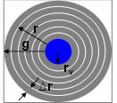
Fig. 2. Concept drawing of dividing half core of planar inductor into many concentric rings.
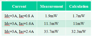
Table 1. Core loss of LTCC inductor with single turn structure.
