


LIBRARY
Analytical Inductance Model for Planner Inductor with Non-uniform Flux Pattern
Year: 2011
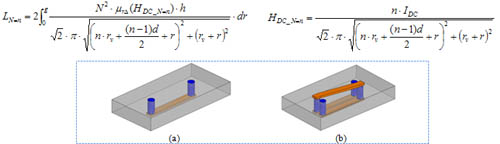
Fig. 1. Planar inductor examples (a) 1-turn structure: N=1, (b) 2-turn structure: N=2.
Fig. 2 shows the concept drawing of using this method on planar inductors shown in Fig.1. Because these inductors have symmetrical structure, Fig. 2 only shows half core. For different planar inductor structures, the shape of concentric ring is different. For single-turn structure (N=1), concentric rings have round shape; for multi-turn structure (N>1), concentric rings have ellipse shape. If the ring width is small enough, flux inside each ring can be assumed as constant. The permeability of each small ring is determined by DC pre-magnetization flux field intensity. The general equations for calculating inductance of these planar inductors are:
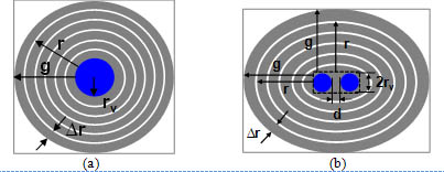
Fig. 2. Concept drawing of dividing half core of planar inductor into many concentric rings (a) 1-turn structure: N=1, (b) 2-turn structure: N=2.
