


LIBRARY
Analysis of EMI Terminal Modeling of Switching Power Converters
Year: 2012
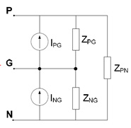
Fig. 1. Three-terminal noise model for terminal EMI modeling.
For this modeling technique, a generic three-terminal Norton equivalent was chosen as the noise model. This is shown in Fig. 1. The model is extracted by taking EMI measurements on the terminals of the converter under different conditions, and then simultaneously solving network equations for each of the conditions. The model was validated with experiments, and the EMI prediction results are shown in Fig. 2.
We have now focused our efforts on understanding the physical nature of EMI noise, as it is important that a connection be established between the model and the physics of the converter. Several points have been investigated, including the key issue of modeling non-linear time-variant converters with linear and time-invariant (LTI) circuits. Our experiments revealed that the parasitic inductance of the dc-bus and the input capacitor provides a constant and dominant impedance at the input of the converter, thus masking its time-variant behavior.
The other issue that was found and investigated was regarding the nature of extracted model impedances. It was found that in the extracted impedances of the terminal model, the real impedance was turning out to be negative at certain frequency points. This is was due to the small amplitude of the measured voltages at those points as well as the smaller size of the real part in comparison with the ideal part of the impedance. The issue was corrected with peak detection during a post-processing step. With these improvements, the impedances now have a physical meaning and the model can be run even in a circuit simulator. This is advantageous as one can now simulate EMI filters, cables, and the like with a terminal model to evaluate their effect on EMI.
Thanks to the investigations above, we have developed a more complete understanding of the limitation and pitfalls of the method, which will help in future development of the method itself.
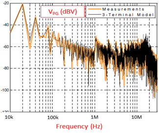
Fig. 2. Prediction of conducted emissions on the LISN from the three-terminal model.
