


LIBRARY
Common-Mode EMI Terminal Modelling of DC-Fed Motor Drives
Year: 2012
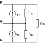
Fig. 1. Generalized three-terminal model of buck-converter based on Norton equivalent.
However, this model has two major limitations. The first limitation is that the models are valid only for one operating point; that is, re-modeling is needed if EMI prediction is needed for a different operating point. The second limitation was that the model is terminated, by which we mean that the load side of the converter is fixed. Thus the model in Fig. 1 can only predict conducted emission on the converter's input side, and once identified, it cannot be used to predict input-side EMI due to changes at the load side. This limitation is due to the black-box nature of the model, which means the load and its associated parasitics have been lumped together in a generic delta-network of impedances (ZPG, ZNG and ZPN). It is impossible to separate the load side from these impedances once the model is extracted.
In aerospace applications, however, the DO-160 standards dictate EMI limits on differential-mode (DM) and common-mode (CM) currents on all harnesses and cable assemblies. Thus for applications like motor drive systems, it becomes necessary to be able to predict changes in conducted emission at the dc side due changes at the ac side or vice versa. To solve this problem, the three-terminal model was modified to predict both dc-side and ac-side EMI noise on a motor drive system. Fig. 2 shows the motor drive and Fig. 3 shows its three-terminal behavioral EMI model. The model is a Thevenin equivalent with two noise sources and a two-port impedance matrix. Currently only CM noise is addressed, as at high frequencies it is the CM noise that is the most troublesome. The model parameters were calculated again by measurements in an in-circuit test. The model was validated by predicting dc-side and ac-side CM noise currents for a CM choke at the dc side and Y-capacitors at the ac side. These predictions are shown in Fig. 4. It is seen that the model predicts well, with the exception of some discrepancies around 1 MHz. At around 1 MHz, the S/N ratio was found to be poor due to the small amplitude of the measured voltages.
The future work includes improvement in model identification and predicting changes in the length of the harness (see Fig. 2). We also plan to research the prediction of EMI for changes in the operating conditions. This model can be very useful in understanding the interaction of dc and ac side EMI in a motor drive system and helping in the development of methods for the co-design of EMI filters for both sides.
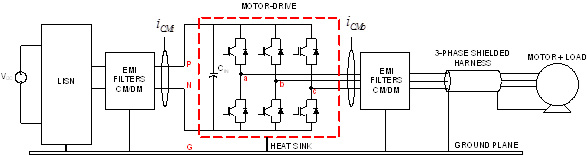
Fig. 2. Set-up of dc-fed motor drive system.
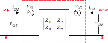
Fig. 3. Terminal model of the motor drive in CM.
