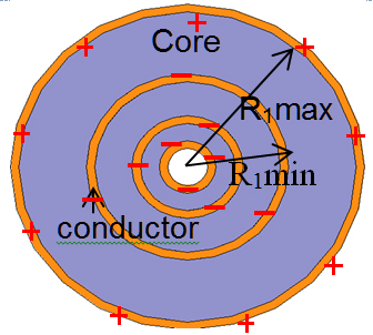
Fig. 1. Cross-section of core of 3-cell "constant-flux" inductor showing conductor and slots with and - indicating the directions of flow of current.
The core and winding of an inductor are designed to distribute flux for distributing energy uniformly in the core to utilize magnetic material throughout the core volume. The structure is designed to avoid crowding of flux for low core loss. The winding is patterned for shorter length and larger area of cross-section for low winding loss. The footprint area of a three-cell inductor is 1.48 times less than that of the conventional toroidal inductor with same energy, maximum flux density, material properties, winding loss, and core loss.

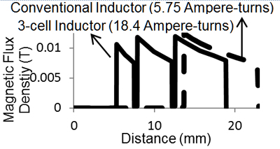
Fig. 2. Line plot of magnetic flux density of the inductor in comparison with that of toroidal inductor with same footprint area and toroidal inductor with same energy
(Solid Line: Magnetic flux density of 3-cell "constant-flux" inductor
Broken Line:Magnetic flux density of toroidal Inductor of equal energy as that of "constant-flux" inductor having 1.48 times smaller foot-print area).

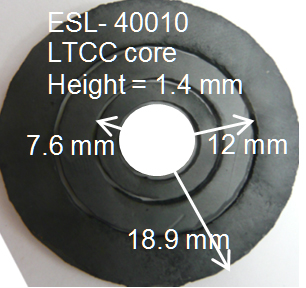
Fig. 3. (a) Three cells of inductor core made of ESL- 40010 LTCC green tape. The height is 1.4mm and the radiuses from the innermost to the outermost cell are 7.6mm, 12mm and 18.9mm, respectively.

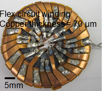
Fig. 3. (b) Three-cell constant-flux inductor with core of 40.5 40.5 2.2 mm3 made of LTCC green tape with relative permeability of 41 and winding of flat copper (of thickness 70 µm) having uniform distribution of flux density with Bmax = 0.015 T.


