LIBRARY
Compensation of DC-Link Pulsation in Single-Phase Static Converters
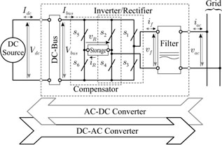
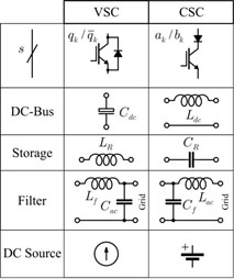
In terms of hardware, compensation of such oscillating power can be achieved by adding an auxiliary leg and a energy storage circuit element to a standard converter. Here, these constitute the oscillating power compensator. The energy storage element is responsible for absorbing and delivering the oscillating power, which is naturally required by a single-phase converter. A general (VSC/CSC) single-phase converter, with power compensator, is presented in Fig. 1(a). Fig. 1(b) illustrates the particular composition for a VSC and CSC, with oscillating power compensation included.
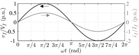
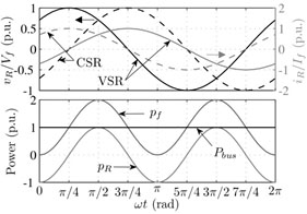
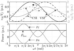
Fig. 2(a) shows AC voltage and current waveforms related to single-phase (VSC/CSC) converters. In Figs. 2(b) and 2(c) are shown the waveforms for the power compensator working as a rectifier and as an inverter, respectively. In order to achieve an effective compensation, the power compensator needs to generate a voltage, as illustrated in Figs. 2(b) and 2(c) (top). In Figs. 2(b) and 2(c) (bottom) is shown the behavior of the power on the AC side, DC bus and the compensator. It is possible to see that the power oscillation does not spread across the converter, so the power in the DC bus is continuous.
