


LIBRARY
External Ramp Autotuning for Current Mode Control of Switching Converters
Year: 2013
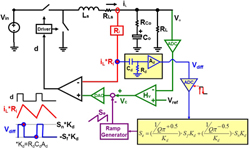
Fig. 1. Peak Current Mode Control with Digital Autotuning Block.
This paper discovers that as long as Se is tuned with the real current slope change (Sn, Sf), Q2 can be well-controlled, since input voltage, output voltage, and inductance variations are exhibited in the current feedback signal (iL*Ri). The high frequency characteristic of Vo(s)/Vc(s) is fixed and immune to those variations, so a high BW design can be achieved. Sn and Sf are sensed by differentiating the current feedback signal with the RC circuit and then sample-and-holding the two slope values. After that, the external ramp for desired Q2 can be calculated by the simple control law in Figure 2.
Finally, simple digital and analog implementations are proposed to realize the autotuning method into peak current mode, valley current mode, and average current mode controllers. Also, they can be used in different topologies without changing control law and tuning circuitry. The simulation and experimental results verified the effectiveness of proposed method, as shown in Fig. 3.
Where Sn and Sf are the rising and falling slope of the inductor current respectively. For the buck converter, Sn=(Vin-Vo)Ri/L and Sf=VoRi/L. Ri is the current sensing gain and L is the filter inductance.
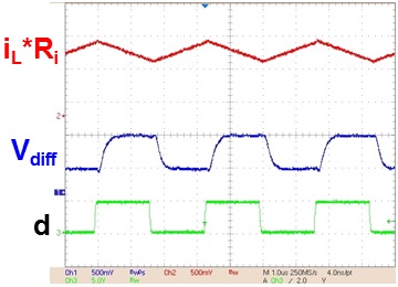
Fig. 2. Measurement of differentiated waveform (Vdiff).
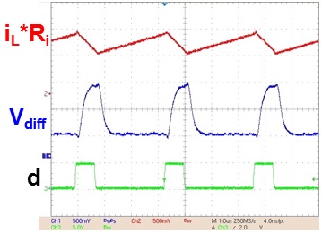
Fig. 2. Measurement of differentiated waveform (Vdiff).
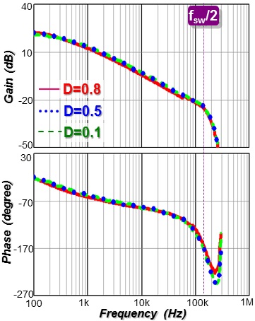
Fig. 3. Measured Vo(s)/Vc(s) with digital autotuning block.
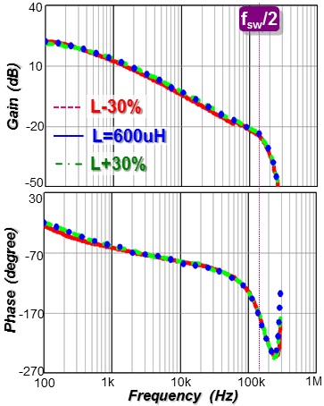
Fig. 3. Measured Vo(s)/Vc(s) with digital autotuning block.
