


LIBRARY
Dual Active Bridge based Battery Charger for Plug-in Hybrid Electric Vehicle with Charging Current Containing Low Frequency Ripple
Year: 2013
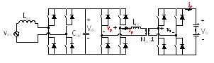
Fig. 1. Battery charger topology with a Full Bridge (FB) AC-DC stage plus a Dual Active Bridge (DAB) DC-DC stage.

The ripple power at two times the line frequency in (1) will compensate the ripple power at the input side, thus ideally the DC link capacitors to store this ripple power can be eliminated. This idea is implemented in a battery charging system comprised of one Full Bridge (FB) AC-DC stage and one Dual Active Bridge (DAB) DC-DC stage. DAB is a promising topology especially for isolated and bi-directional power conversion. It has many benefits, such as Zero Voltage Switching (ZVS) for both primary and secondary bridges, small passive sizes, utilization of parasitic and fixed switching frequency. The DAB ZVS range is shown in Fig.2 when phase shift modulation is used. It can be seen that hard switching of the devices, either in the primary bridge or the secondary bridge, always happens due to the severe variation of the sinusoidal output current. In order to realize sinusoidal charging, the control schemes in Fig. 3 is proposed. Since the transfer function from phase-shift to output current can be modeled as a constant gain, the main part of the dynamic behavior of the DAB will be determined by the low pass filter used to attenuate the high frequency current ripple at the output. The experimental results are shown in Fig. 4.
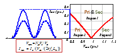
Fig. 2. DAB ZVS analysis with phase shift modulation.
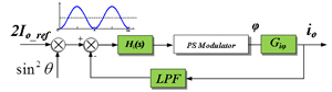
Fig. 3. Block diagram of the control loop.
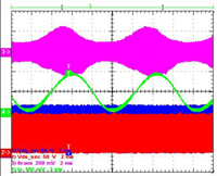
Fig. 4. Experiment results of sinusoidal charging.
