


LIBRARY
Modulation Methods Comparison for Neutral-Point-Clamped Three-Phase Inverters
Year: 2013
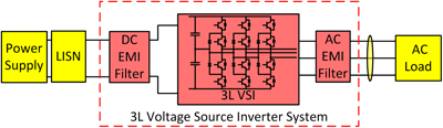
Fig. 1. Three level voltage source inverter system.
Based on the detailed implementation of the three modulation methods, system performance on CM noise reduction, NP voltage ripple and semiconductor losses are analyzed and compared in detail. The results show that CMR modulation can help to reduce both DM and CM noise in the EMI range. CME modulation will increase system DM noise but it can help to reduce the CM noise, while the benefit of CME modulation is highly related to the DT in the system. The analytical calculation method of the NP voltage ripple is discussed in detail and both analytical and experimental results are shown to compare the NP voltage ripples using three different modulation method. Moreover, the loss calculation is also discussed in the paper, the analytical calculation result is shown, which shows that the losses are comparable between NTSV and CME modulation while CMR modulation can reduce the switching losses by about 30%.

Fig. 2. switching states in 3L VSI.
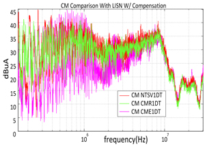
Fig. 3. CM current spectrum.
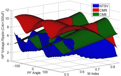
Fig. 4. NP voltage ripple comparison.
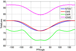
Fig. 5. Device loss comparison.
