


LIBRARY
Ripple Power Balance Analysis on Plug-in Hybrid Electric Vehicle Charger with Sinusoidal Charging
Year: 2013
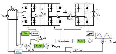
Fig. 1. Battery charger topology with a Full Bridge (FB) AC-DC stage plus a Dual Active Bridge (DAB) DC-DC stage.

The ripple power at two times the line frequency in (1) will compensate the ripple power at the input side, thus ideally the DC link capacitors to store this ripple power can be eliminated. However, non-ideal effects, such as control delay and converter losses will cause ripple power imbalance, and increase on the DC link voltage ripple if the capacitance is fixed. For example, constant conversion loss in the AC/DC stage can be represented by an equivalent paralleled resistor in the converter average model of Fig. 2, then the ripple power between input and output becomes imbalanced. The ripple power in the DC link capacitor will be

To solve this issue, the imbalance can be compensated by controlling the output current in the form of (b) in Fig. 3. With the proposed loss compensation control scheme, the dc link voltage ripple can be reduced from 16.8V to 19.9V with only 10% compensation. It is a 15.6% reduction, as shown in Fig. 4.
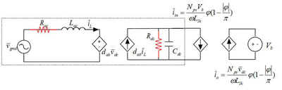
Fig. 2. Average model of topology considering constant loss in AC/DC stage.
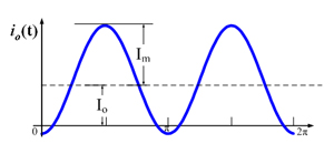
Fig. 3. Output current waveform with loss compensation.
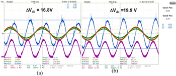
Fig. 4. Experimental results of DC link voltage ripple.
