


LIBRARY
Design and Implementation of Three-phase AC Impedance Measurement Unit (IMU) with Series and Shunt Injection
Year: 2013
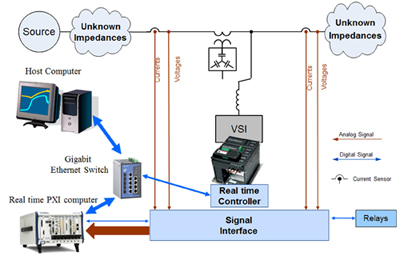
Fig. 1. Impedance measurement system function block diagram.
The most critical issue is to increase the SNR without increasing the IMU injection level. SNR is improved by using:
- both shunt and series injection modes to improve the perturbation distribution between source and load and to enhance the response signal SNR;
- analog filtering and oversampling to increase the resolution of the AD conversion;
- correlation between the reference of injected signal and the measured perturbation to reduce the uncorrelated noise present in the measurement system.
Figure 1 illustrates the function that blocks the IMU. It uses a voltage source inverter to create perturbation, a PXI computer for sampling and real time signal processing, and a PC for data offline processing to get the final impedance result. The assembled hardware is shown in Figure 2.
The performance of the designed measurement unit is tested with a low-output-impedance source. Both linear and nonlinear loads are measured and the results show good matching with the theoretical and simulation values. The proposed IMU is also scalable to higher power applications and it is an important instrument to investigate stability in electrical power system applications as in microgrid, aerospace, naval and transportation applications.
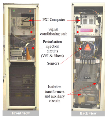
Fig. 2. Front and Back view of the IMU.
