


LIBRARY
High-Frequency Model of a Transformer for Conducted EMI Analysis
Year: 2013
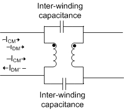
Fig. 1. 2-winding transformer.
An accurate simulation model is needed for each component of the power converter to analyze the complete system. With this goal in mind, a high-frequency model of the transformer (Fig. 1) used in a commercial battery charger system is proposed. The simulation results are verified against the measured data.
The existing high frequency models are not able to accurately predict the impedance, either common- or differential-mode, over a wide frequency range (10 kHz- 110 MHz). The existing methods for modeling a choke ignore the inter-winding capacitance for simplicity. This is not the case for a transformer, and hence a new lumped circuit model is proposed in Fig. 2. The coupling factors kC and kD are adjusted so that the common-mode current does not have any effect on the differential-mode elements and vice-versa.
A series or parallel R-L-C combination is used to predict the predominant capacitive or inductive behavior of the common- or differential-mode impedance, respectively. The no. of resonance peaks determines the number of stages of R-L-C used.
The simulation model is obtained by numerically fitting a lumped circuit of R-L-C in MATLAB to the measurement results. Finally, all the passives are combined to obtain the complete high-frequency model of the transformer, and the impedance measured in different configurations is compared against the Saber simulation model. The results of the common-mode impedance are shown in Fig. 3; it is within 3 dB of the measured result.
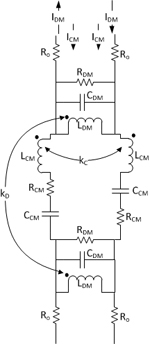
Fig. 2. Proposed high frequency model of 1:1 transformer to predict the first resonance peak.
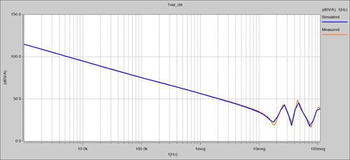
Fig. 3. Comparison of common-mode impedance by measure-ment and the simulation model.
