LIBRARY
Improved Procedure to Design Coupled Inductors Based on Geometry Constant

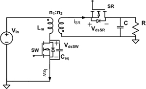
A design example of coupled inductors is shown to illustrate the entire design procedure. The planar coupled inductors are utilized in the Quasi-Square-Wave (QSW) flyback converter shown in Fig. 1 with a switching frequency of 5 MHz and an output power of 30 W. The turns-ratio is 4:1 and the magnetizing inductance is 1 µH.
After surveying the commercial magnetic materials for a 1-5 MHz operation, Ni-Zn ferrite (4F1) is chosen to be the core material. The geometrical constant Kg, as a measure of the effective magnetic size of a core, is used to select the core dimensions for the application. The criterion of core selection is derived in (1). Because of thermal limitations in the core material, a flux density "B was limited to 10 mT. The value of the left side, which is related to the core ge-ometry, needs to be as close as possible to the value on the right side, which is based on electrical specifications and Steinmetz coefficients of the material.

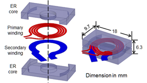
The coupled inductors are shown in Fig. 2 with a size of ER 183.210 mm, a two-layer PCB winding with top and bottom 70-µm-thick copper and 0.127-mm-thick dielectric material.
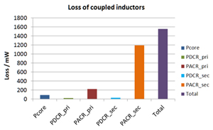
Fig. 3 shows the loss breakdown of the coupled inductors. The overall loss exhibited 5.2% of 30 W output power. In the future, a proximity effect will be taken into consideration to optimize the design.


