


LIBRARY
Size and Weight Dependence of the Single Stage Input EMI Filter on Switching Frequency for Low Voltage Bus Aircraft Applications
Year: 2013
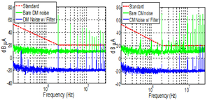
Fig. 1. 2 MHz noise spectrum.
Experiment results show that the EMI filter was larger and heavier for the 2 MHz case (Fig. 4) due to high frequency noise spikes at tens of mega-hertz (Figs. 1-2). This conclusion was made based on the low frequency attenuation requirement. However, in the hardware implementation the real limitation comes from the spectrum at high frequencies, 20 MHz - 30 MHz. The problems at high frequencies arise from several different factors. First, the permeability of the nanocrystaline material drops significantly with the frequency, thus making this material less effective in the 20 MHz - 30 MHz range. Secondly, parasitics of the filter components, such as the ESL of the capacitors and EPC of the inductors, degrade the performance of the filter. The conclusions of this paper are limited to the assumptions and approaches taken, such as single stage passive filtering, magnetics materials choice, no integration (Fig 3) and the design procedure.
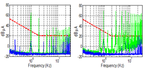
Fig. 2. 1 MHz noise spectrum: left - DM Noise; right - CM noise.
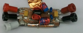
Fig. 3. 1 MHz EMI filter.
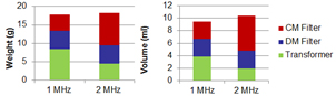
Fig. 4. Converter magnetics volume and weight for 1 MHz and 2 MHz.
