


LIBRARY
EMI Filter Design and Optimization for Both AC and DC Side in a DC-fed Motor Drive System
Year: 2013
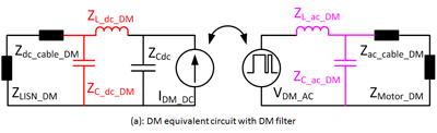
Fig. 1. Equivalent circuits for EMI filter analysis.
Considering that the CM noise is going though both the AC and DC side, and there is no such big low impedance path as the dc link capacitor in DM propagation path, the equivalent circuit includes the interaction between the AC and DC side for the CM noise. Adding an EMI filter on one side will influence the EMI noise level on the other side. If this interaction is not considered in the filter design procedures, even though one can design an optimized filter for one side to meet the standard, adding a filter on the other side will make the noise worse on this side and finally fail to meet the standard. To minimize the impact on the EMI noise of one side caused by adding a filter on the other side, a certain design order must be followed to design the AC, DC, CM and DM filters. Fig.1 shows an optimized design procedure for designing both AC and DC filters. Using this method, both AC and DC noises can meet the standard.
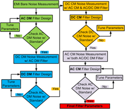
Fig. 2. EMI filter design sequence for both AC and DC Side.
