Become a Member
Become a Member

LIBRARY

Modeling the Output-Impedance Negative Incremental Resistance Behavior of Grid-Tied Inverters

Year: 2014
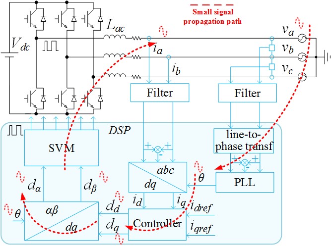
Fig. 1. Grid-tied inverter with current loop and PLL.
Three-phase grid-tied inverters are widely installed in micro-grids to utilize renewable energy such as solar and wind energy. The stability issue caused by grid-tied inverters can be studied using an impedance based method. This paper models the output impedance of the grid-tied inverter shown in Fig. 1. The model shows that the output impedance of a grid-tied inverter in dq frame has a negative resistance feature in a qq channel. This is however, a result of the Phase-Locked Loop (PLL) influence on the converter dynamics, which function is to do grid synchronization. As shown in Fig. 1, perturbation from the grid voltage will propagate to the output angle of PLL, then to the duty cycle applied to the converter power stage, and finally to the output current of grid-tied inverter. PLL dynamic shapes Zqq as a negative incremental resistance with in its bandwidth. Fig. 2 shows the comparison between model and measurement results. Both model and experimental results shows the negative resistance feature of Zqq.

Another interesting and important feature of Zqq is that it has a right half plane (RHP) pole. The frequency of the RHP pole changes along with the PLL bandwidth and current rating of the inverter as shown in Fig. 3.

These features indicate that the grid-tied inverter is a source converter that has a negative incremental resistance. When the Nyquist stability criteria is applied and the grid-tied inverter is treated as a source converter, the number of encirclements of the critical point (-1, 0) should be equal to the number of RHP poles in the system. Alternatively, the inverse Nyquist criteria can be used since there is no right half plan zero in the system.


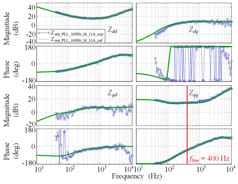
Fig. 2. Grid-tied inverter output impedance measurement.
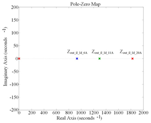
Fig. 3. Pole-zero map of grid-tied inverter output impedance.

Our Industry Partners