


LIBRARY
%u201CPlanar Inductor Structure with Variable Flux Distribution%u201D - A Benefit or Impediment?
Year: 2014
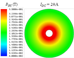
Fig. 1. DC flux distribution of planar disc core.
Fig. 1 shows the top view of the DC flux distribution of the disc core with 20A DC current, from which it can be seen the disc core is excited in a large DC bias range. The inner core is almost saturated while the outer core is still running at a relatively low bias point. Because of the saturation, the permeability of the inner core is decreased to a very low value. Therefore, the AC flux avoids the inner core, where the magnetic reluctance is large. Fig. 2 illustrates the AC flux distribution of the disc core with 20A DC bias current and 6A peak-to-peak AC current ripple. It can be seen that the AC flux is automatically pushed to the outer core.
Due to the DC and AC flux counterbalance mechanism, the core loss density of the inner saturated core is limited. The peak Pv point is neither the maximum DC nor AC flux points.The operating points of the disc core are extended into saturated region, where there is better core utilization. The AC flux and core loss (i.e. the area of the minor loop of the BH curve shown in Fig. 4) is automatically reduced. The saturation is no longer detrimental in this special structure.
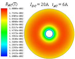
Fig. 2. AC flux distribution of planar disc core.
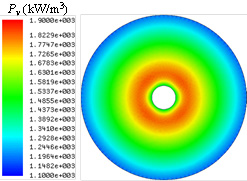
Fig. 3. Core loss density distribution of disc core.
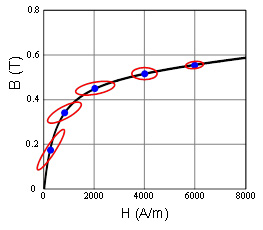
Fig. 4. Multiple operating points of the disc core.
