


LIBRARY
Inductor Geometry with Improved Energy Density
Year: 2014
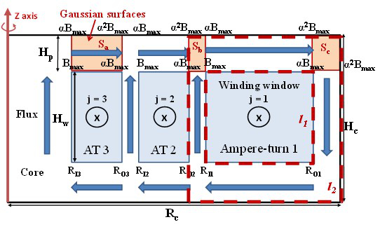
Fig. 1. Ideal constant-flux inductor geometry.
Based on the enclosed-winding geometry, the behavioral model of the constant-flux inductor can be constructed in such a way that it shapes the flux distribution and estimates the perfor-mance of the inductor. As shown in Fig. 1, an ideal constant-flux inductor with enclosed winding consists of a magnetic core with Nw winding windows carrying prescribed Ampere-turns ATj. The objective is to synthesize the Ampere-turns to constrain the flux variation to a "uniformity factor " ratio of the minimum flux density Bmax to the maximum flux density Bmax allowed in the magnetic field around winding window j. "Constant" flux is achieved when approaches unity. The model is modified to achieve a prescribed , as well as the optimal design for a constant-flux inductor.
Fig. 2 gives an example of the relationships among the current rating, inductance, and dc resistance when the relative permeability changes from 20 to 30. Along each curve, the current rating is fixed while the relative permeability is swept from 20 to 30. Either a smaller permeability or a smaller current rating would increase the number of turns that each winding window represents in order to maintain the maximum flux density Bmax. By selecting the optimal variables, the performance of the inductor can be significantly improved.
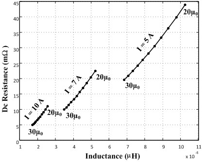
Fig. 2. Relationship among inductance, dc resistance, permeability and current rating.
