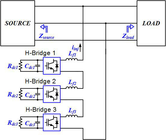
Figure 1. Multi-level single-phase shunt current injection converter based on cascaded H-bridge topology.
This paper describes the detailed design of a single-phase multi-level single-phase shunt current injection converter based on cascaded H-bridge topology. The shunt current injection converter can inject an arbitrary current perturbation at three-phase power system interfaces, in order to identify small-signal dq impedances. Special attention is given toward the selection of inductors and capacitors, trying to optimize the selected component values. The proposed control is extensively treated and inner current and outer voltage loops are completely analyzed. Furthermore, voltage balancing is included into the control to assure dc voltage control for each H-bridge module. Analytical expressions, which describe the design procedure, are derived and verified to be accurate. The designed converter is simulated using a detailed switching simulation model and excellent agreement between theory and simulation results are obtained. The proposed multi-level single-phase converter is a natural solution for single-phase shunt current injection with the following properties: modular design, capacitor energy distribution, reactive element minimization, higher equivalent switching frequency, capability to inject higher frequency signals, suitable to perturb higher voltage power systems and capable of generating cleaner injection signals.
The first simulated operating point investigates waveforms when low frequency (50 Hz) current is being injected into the grid, this operating point is equivalent to 10 Hz injection in dq coordinates. Thus, in this operating point a low frequency voltage ripple at 10 Hz is present in dc capacitor voltages. Another critical operating point is a high frequency injection of 30 A rms, 1 kHz current into the system. Figure 2 shows simulation waveforms that verify proper operation when the converter is injecting a 50 Hz sinusoidal signal. The dc voltages are balanced among themselves and a 10 Hz ripple is slightly below 60 V, which is accurately predicted by analytical expressions.
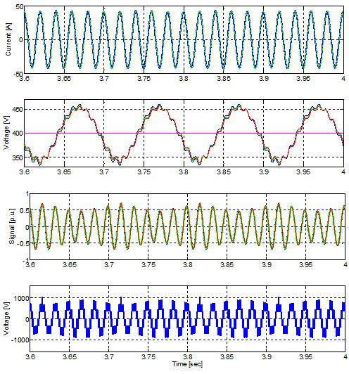
Figure 2: Simulation waveform signals for 50 Hz injection operating point (a) inductor current ilf and current reference iref (b) dc voltages vdc1, vdc2, vdc3 (c) duty cycles d1, d2, d3 (d) switching voltage.


