


LIBRARY
Power-Cell Switching-Cycle Capacitor Voltage Control for Modular Multilevel Converters
Year: 2014
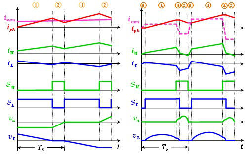
Fig. 1: Comparison between conventional control and SCC.
The SCC is described as shown in Fig.1. In the case where the phase current is positive, the state ③ is applied right before state ① to control the lower arm current to an offset value such that in the time duration of the state ① the average current flowing through the lower capacitor is controlled back to zero. Similarly, the SCC arranges the state ④ right before state ② to control the upper arm current to an offset value such that in the time duration of the state ② the average current flowing through the upper capacitor is controlled toward zero. This method can be easily extended to the situation when the phase current is negative, which will be elaborated in the full paper.
The simulation waveforms of the single-module-per-arm are shown in Fig.2, where a 13% p.u. capacitance and a 0.22% arm inductance are used to achieve a 2% capacitor voltage ripple with switching frequency at 1.98 kHz, compared to the implementation with the conventional control approach in which at least 100% p.u. capacitance and 22% arm inductance are required to achieve the same goal. The simulations with more module counts at variable line frequencies will be shown in the full paper, and the semiconductor loss will be estimated and compared to conventional control approaches as well.
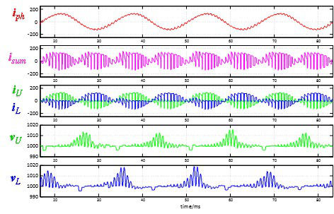
Fig. 2: Simulation waveform.
