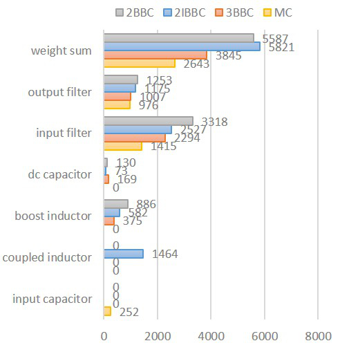
Fig. 1. Weight distribution of AC-AC converters.
The Matrix Converter (MC) is considered a main candidate for the next generation industrial motor drive, and more recently for "more electric aircraft" applications. EMI related phenomena are especially relevant in cases where its containment is of great concern - as in air-craft power systems, and as such they remain as the gap separating the MC from its actual deployment. Hence, the need for a comprehensive design procedure for EMI filters in MC appli-cations is apparent. This comprises an appropriate model to predict the conducted EMI emissions of the MC, both in common-mode (CM) and in differential-mode (DM), and the actual filter design procedure. Further, if both input and output terminal EMI filters are required - as in the case under consideration, then the design procedure should address both filters simultaneously. This is as opposed to the dc-link based ac-to-ac power converters where typically input and output filters are designed assuming decoupled input and output noise. Lastly, to verify the power density of the filter designed, the weight and volume of the passive components should be carefully calculated too. The last step above allows the designer to verify the level of compactness achieved, a critical aspect since MCs are usually assumed to feature a higher power density than indirect power converters, an assumption which is based solely on the fact that the MC power stage lacks dc-link capacitors, without considering the impact of EMI filters. In this case, a comparison against alternative back-to-back converters ensures that the MC is indeed the best solution. In this paper specifically, two- and three-level voltage-source converters are used as possible alternatives for the design of the motor drive in question.
In this regard, this paper presents a detailed design procedure for the input and output EMI filters of an MC motor drive rated at 30 kW, driving a permanent magnet synchronous machine (PMSM). The procedure is based on frequency domain analysis of the EMI sources and con-duction paths, where the input and output CM filters are designed simultaneously due to the coupling of the CM path.
A comparison between the estimated EMI filter weight of the MC, and a two-level back-to-back converter (2BBC), two-level interleaved back-to-back converter (2IBBC), and three-level back-to-back converter (3BBC) is conducted using the proposed design procedure for all converters in question. This shows the advantage of the MC where high power density is desired.


