


LIBRARY
Assessment of Switching Frequency Impact on EMI Emissions of 10 kW SiC Power Converter Using Un-terminated Behavioral Models
Year: 2014
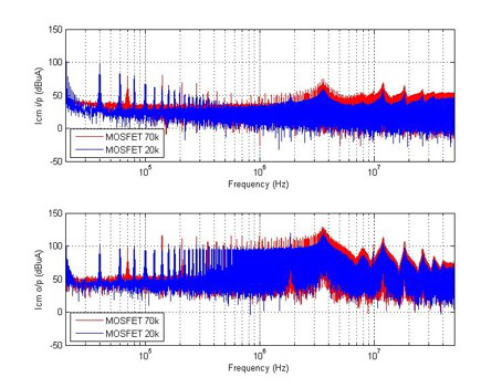
Fig. 1. DM input/output current with 20k and 70k switching frequency in frequency domain.
Un-terminated EMI behavioral modeling can describe the three-phase inverter with two noise sources and three inverter impedance parameters. The inverter model and EMI model are shown in Fig. 3. This model is accurate in predicting the DM and CM noise for most practical input and output conditions of an inverter. However due to the limitation of the measurement, it's difficult to have the amplitude of the frequency component above 10MHz during an experiment. Therefore the accuracy for the un-terminated model above 10MHz is uncertain. Pushing the switching frequency higher will help to provide high-frequency components of larger amplitude.
In terms of the model, when the switching frequency goes high, the equivalent noise sources of the inverter will increase, as shown in Fig. 4, and the equivalent impedances are likely to remain unchanged, as shown in Fig. 5. This result will help understand the EMI analysis at the system level with different switching frequencies, and to design appropriate EMI filters. The model runs in the frequency domain and is validated with experiment on a SiC MOSFET inverter.
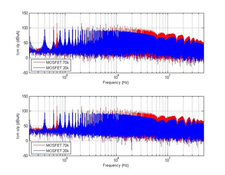
Fig. 2. CM input/output current with 20k and 70k switching frequency in frequency domain.
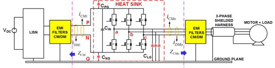
Fig. 3. (a) Un-terminated CM EMI behavioral model: The inverter model.
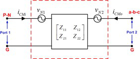
Fig. 3. (b) The extracted model.
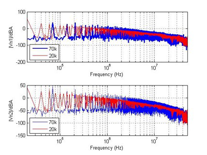
Fig. 4. The equivalent noise sources of the un-terminated behavioral inverter model.
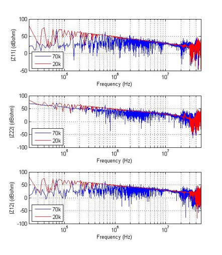
Fig. 5. The equivalent impedance matrix of the un-terminated behavioral inverter model.
