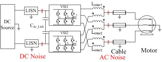
Fig. 1. Interleaved 2L dc-fed motor drive system.
Adjustable-speed motor drives with a voltage-source pulse-width modulation inverter with long cables cause EMI issues. Usually EMI filters are made part of the system to meet EMI requirements, and these filters make up a big portion of the system weight. To improve system power density and reliability, paralleled and interleaved converter topology is commonly used. Fig. 1 shows the topology of an interleaved two-level dc-fed motor drive system. By phase-shifting the carrier waveform of individual converters with an appropriate angle, the voltage harmonics and EMI noise can be reduced, and the line inductor and EMI filter weight can also be reduced, as shown in Fig. 2.
However, interleaving also creates a voltage difference between the two converters, and requires interphase inductors to limit the circulating current. The additional weight of interphase inductors make the passive component heavier in the interleaving topology in motor drive applications. In order to reduce the total weight of passive components, an interphase inductor can be integrated with the load indcutor or DM inductors in the EMI filter with negligible increase in the weight, as shown in Fig. 3. The maximum integrated inductance is related to the interleaving angle and system operation conditions, which can be designed analytically.
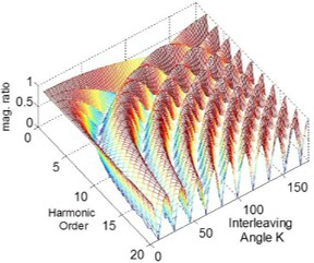
Fig. 2. (a) Impact of Interleaving with different Interleaving angles: On-voltage harmonics.
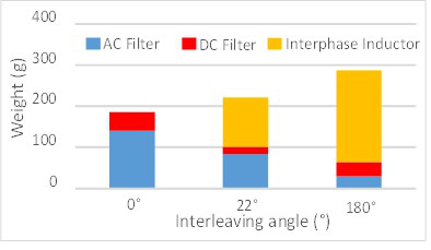
Fig. 2. (b) Passive component weight reduction.
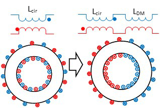
Fig. 3. (a) Integration and design results of interphase inductors: Integration of interphase inductors.
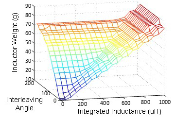
Fig. 3. (b) Integrated inductor design results.


