LIBRARY
30-W Flyback Converter Operating at 5 MHz

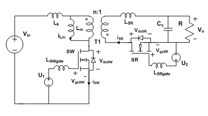
The baseline for this investigation is the class of converters with voltages of 36-72 V down to 12 V at 0 - 30 W. Around 5 MHz would be a suitable switching frequency, considering the introduction of GaN transistors on the market in the last few years. To mitigate switching loss, the quasi-square-wave flyback converter with synchronous rectifier was selected, as shown in Fig. 1.
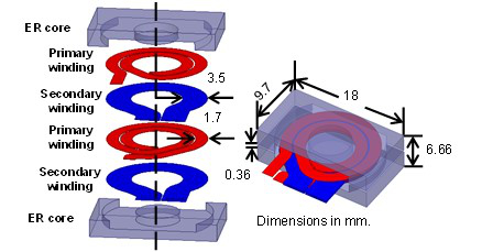
Nickel-zinc (NiZn) ferrite 4F1 with a relative permeability of 80 was selected as the magnetic material since it had low loss in the 5 - 10 MHz range. Fig. 2 shows the planar coupled inductors with 0.96 µH of magnetizing inductance and a size of ER 18x3.210 mm3, which were fabricated with a leakage inductance of 30 nH. In addition, the high dv/dt of 16 V/ns and high di/dt of 10 A/ns caused by the smaller output capacitance of GaN FETs necessitated negative 2 V between the gate and the source to prevent false turn-on of the switches.
The peak efficiency is 90.6% at a full load of 30 W, with ZVS achieved for both switches. The switching losses are the dominant losses (36.5%) of the total loss because of the large turn-off current for both switches; 35.3% of total losses are incurred in the coupled inductors; 66.1% of magnetic loss is the winding loss, due to the skin and proximity effects in the megahertz range. With the same power level and efficiency, the power density is 14% better than that of the commercial flyback converter.
The bulkiest component is the coupled inductor, and the flux density is the dominant parameter to determine the core size, which is constrained by the material properties. Future research will be focused on magnetic design to further decrease the winding loss and volume.


