LIBRARY
Equivalent Circuit Model and Design of Constant On-time Current Mode Control With External Ramp Compensation


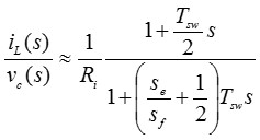
The external ramp will make the circuit behave as a non-ideal current source, as it will bring one moving pole, which is related to the magnitude of the external ramp, and one static zero, which is located at fsw/π. The proposed equivalent circuit to represent this non-ideal current source is shown in Fig. 1(b). Where the Re2-Le2 branch is utilized to resemble the non-idealness of this current source. Re2 and Le2 form a static zero while Re2, Le2 and Ls form the moving pole. For a large duty cycle application, there is an additional double pole, which is shown by a Re-Ce branch resonating with the power stage inductor. The three-terminal switch equivalent circuit model is shown in Fig. 2, where all the transfer functions (control-to-output, output impedance, input impedance and audio susceptibility) can be examined and extended very easily to multi-phase case. This equivalent circuit model is an extension of the original three-terminal current mode control by adding a Re2-Le2 branch that resembles the effect of the external ramp in constant on time control.


